Transcription of Model Q46P pH Monitor - Analytical Technology, Inc.
1 O & M Manual Model q46p pH Monitor Home Office European Office Analytical Technology, Inc. ATI (UK) Limited 6 Iron Bridge Drive Unit 1 & 2 Gatehead Business Park Collegeville, PA 19426 Delph New Road, Delph Phone: 800-959-0299 Saddleworth OL3 5DE 610-917-0991 Phone: +44 (0)1457-873-318 Fax: 610-917-0992 Fax: + 44 (0)1457-874-468 Email: Email: 2 O&M Manual Rev-F (8/17) Table of Contents PART 1 - INTRODUCTION .. 4 General .. 4 Features .. 5 q46p System Specifications.
2 6 q46p Performance Specifications (Common to all variations) .. 7 General Q25P pH Sensor .. 7 Sensor Features .. 8 Q25P Sensor Specifications .. 8 PART 2 ANALYZER MOUNTING .. 10 General .. 10 Wall or Pipe Mount .. 11 Panel Mounting .. 13 PART 3 SENSOR/FLOWCELL MOUNTING .. 14 General .. 14 Flow Tee Mounting .. 15 Union Mounting .. 16 Submersion Mounting .. 17 Insertion Mounting .. 18 Conventional pH Sensors .. 20 Sealed Flowcell .. 21 Flow Tee Adapter .. 22 Lock-n-Load System .. 23 PART 4 ELECTRICAL INSTALLATION .. 24 General .. 24 Power Connection .. 24 Relay Connection .. 26 Optional Output or Relay Connections.
3 27 Sensor Wiring .. 28 Direct Sensor Connection .. 31 Junction Box Connection .. 32 Combination Electrode Connection .. 33 External Preamplifier .. 35 PART 5 CONFIGURATION .. 36 User Interface .. 36 Keys .. 37 Display .. 37 Software .. 38 Software Navigation .. 39 Measure Menu [MEASURE] .. 41 Calibration Menu [CAL] .. 42 Configuration Menu [CONFIG] .. 42 Control Menu [CONTROL] .. 47 Diagnostics Menu [DIAG] .. 51 PART 6 CALIBRATION .. 55 Overview and Methods .. 55 Sensor Slope .. 55 Sensor Offset .. 55 2-Point Calibration Explained .. 56 1-Point Calibration Explained .. 56 Performing a 2-Point Calibration.
4 56 Performing a 1-Point Calibration .. 57 Temperature Calibration .. 58 PART 7 PID CONTROLLER DETAILS .. 60 PID Description .. 60 PID Algorithm .. 60 Classical PID Tuning .. 62 Manual PID Override Control .. 62 Common PID Pitfalls .. 62 PART 8 MAINTENANCE AND TROUBLESHOOTING .. 64 System Checks .. 64 Instrument Checks .. 64 Display 65 Cleaning the Sensor .. 67 Replacing the Saltbridge and Reference Buffer Solution .. 68 Troubleshooting .. 69 SPARE PARTS .. 71 3 O&M Manual Rev-F (8/17) Table of Figures FIGURE 1 Q46 ENCLOSURE DIMENSIONS .. 10 FIGURE 2 - WALL OR PIPE MOUNTING BRACKET.
5 11 FIGURE 3 - WALL MOUNTING DIAGRAM .. 12 FIGURE 4 - PIPE MOUNTING DIAGRAM .. 12 FIGURE 5 - 115/230 VAC PANEL MOUNT & CUT-OUT .. 13 FIGURE 6 - Q25 SENSOR TYPES .. 14 FIGURE 7 - FLOW THROUGH TEE MOUNT .. 15 FIGURE 8 - " UNION MOUNT .. 16 FIGURE 9 - SENSOR SUBMERSION MOUNT .. 17 FIGURE 10 - SENSOR INSERTION MOUNT .. 18 FIGURE 11 - CPVC SENSOR INSERTION MOUNT .. 19 FIGURE 12 - (63-0013) COMBINATION PH SENSOR, FLOW TYPE .. 20 FIGURE 13 - (63-0009) COMBINATION PH SENSOR, SUB. TYPE .. 20 FIGURE 14 - SEALED FLOWCELL DETAILS .. 21 FIGURE 15 - TWIST-LOCK FLOW TEE .. 22 FIGURE 16 - LOCK-N-LOAD SENSOR EXPLODED 23 FIGURE 17 Q46 25 FIGURE 18 Q46 RELAY CONNECTIONS.
6 26 FIGURE 19 - OPTIONAL RELAY BOARD WIRING .. 27 FIGURE 20 - OPTIONAL ANALOG OUTPUT WIRING .. 27 FIGURE 21 - CABLE DESCRIPTION, Model Q25P .. 28 FIGURE 22 - DETACHABLE SINGLE SHIELDED CABLE, Model Q25P .. 29 FIGURE 23 - q46p SENSOR CONNECTIONS .. 30 FIGURE 24 - SENSOR CABLE PREPARATION .. 31 FIGURE 25 - JUNCTION BOX INTERCONNECT WIRING .. 32 FIGURE 26 OEM SENSOR CONNECTIONS, COMBINATION ELECTRODES .. 33 FIGURE 27 ATI COMBINATION ELECTRODE CONNECTIONS .. 34 FIGURE 28 - EXTERNAL PREAMP FOR CONVENTIONAL SENSOR WIRING .. 35 FIGURE 29 - USER INTERFACE .. 36 FIGURE 30 - SOFTWARE MAP .. 40 FIGURE 31 - AUTOMATIC PH BUFFER TABLES.
7 44 FIGURE 32 - AUTOMATIC PH BUFFER TABLES (CONT D) .. 45 FIGURE 33 - CONTROL RELAY EXAMPLE, HYSTERESIS AND OPPOSITE PHASE .. 49 FIGURE 34 - ALARM RELAY EXAMPLE .. 50 FIGURE 35 - Q45H ISA (IDEAL) PID EQUATION .. 60 FIGURE 36 - REPLACING THE SALTBRIDGE AND REFERENCE BUFFER .. 69 4 O&M Manual Rev-F (8/17) Part 1 - Introduction General The Model q46p provides continuous measurement of pH in aqueous systems. It is suitable for potable water, wastewater, and a wide variety of process water applications. q46p monitors may be used with Q25P differential pH sensors or a variety of conventional combination pH sensors.
8 Monitors are available in two electronic versions, a universal AC powered Monitor for operation from 90-260 VAC and a 12-24 VDC unit. Both versions provide two 4-20 mA analog outputs and 3 SPDT relays. One analog output may be configured for PID control and one of the relays may be configured to provide a remote trouble indication. The q46p is available with a few options to expand the capabilities of the Monitor . Users may select either a third analog 4-20 mA output or an expansion card that provides three additional low voltage SPST relays. The expansion relays are not isolated from each other. This Monitor also provides digital communication capability.
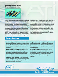
9 Users may order Q46 systems with either Profibus DP, Modbus RTU, or Ethernet communications boards factory installed. ATI q46p pH System Part 1 Introduction 5 O&M Manual Rev-F (8/17) Features Standard q46p Analyzers have fully isolated inputs and outputs. Analog outputs are additionally completely isolated from each other. Available in either 90-260 VAC or 12-24 VDC power supply systems. All features remain the same in both variations. Output Hold, Output Simulate, Output Alarm, and Output Delay Functions. All forced changes in output condition include bumpless transfer for gradual return to on-line signal levels to avoid system control shocks on both analog outputs.
10 Three 6 amp SPDT relay outputs and two analog 4-20 mA outputs are standard. Software settings for relay control include setpoint, deadband, phase, delay, and failsafe. An optional 3-relay card, for 0-30 V signals, is available to bring the total to 6 relays. Selectable PID controller on main analog output. PID controller can operate with instrument configured as loop-power analyzer or as one of the two outputs on the AC powered instrument. PID includes manual operation feature, and diagnostic stuck-controller timer feature for alarm output of control problems. Digital communication option for Profibus-DP, Modbus-RTU.