Transcription of Modeling and Analysis of a Surface Milling Cutter Using ...
1 International Journal of Engineering Research and Development e-ISSN: 2278-067X, p-ISSN : 2278-800X, Volume 4, Issue 10 (November 2012), PP. 49-54 49 Modeling and Analysis of a Surface Milling Cutter Using finite Element Analysis Reddy1, Swamy2 1PG Student, Department of Mechanical Engineering, University College of engineering, 2 Department of Mechanical Engineering, University College of engineering, JNTUK- Kakinada, , INDIA Abstract:- Milling is one of the progressive enhancements of miniaturized technologies which have wide range of application in industries and other related areas. Milling like any metal cutting operation is used with an objective of optimizing Surface roughness at micro level and economic performance at macro level. In addition to Surface finish, modern manufacturers do not want any compromise on the achievement of high quality, dimensional accuracy, high production rate, minimum wear on the cutting tools, cost saving and increase of the performance of the product with minimum environmental hazards.
2 Interactive (three-dimensional) solid Modeling is used in the development of relatively efficient and fast solutions to the many constraints and/or limitations encountered in the design process. In this Paper the design aspects of Surface Milling Cutter is analyzed. The objective considered is the design and Modeling of Surface Milling Cutter and to analyse various stress components acting on it. Various designing strategies are considered to design the effective Surface Milling Cutter like outer diameter, inner diameter, radius, teeth angle etc .The design and Analysis is carried out Using the softwares like CATIA V5 and ANSYS Keywords:- ANSYS, CATIA, Cutter , high Speed Steel, Milling , Speed I. INTRODUCTION Machining is undoubtedly the most important of the basic manufacturing processes, since industries around the world spend billions of dollars per year to perform metal removal. That is so, because the vast majority of manufactured products require machining at some stage in their production, ranging from relatively rough operations to high -precise ones, involving tolerances of mm, or less, associated with high quality Surface finish.
3 It is estimated that today, in industrialized countries, the cost of machining accounts to more than 15% of the total value of all products by their entire manufacturing industry, whether or not these products are mechanical.. Milling is a process of producing flat and complex shapes with the use of multi-tooth cutting tool, which is called a Milling Cutter and the cutting edges are called teeth.[1] The axis of rotation of the cutting tool is perpendicular to the direction of feed , either parallel or perpendicular to the machined Surface . The machine tool that traditionally performs this operation is a Milling machine. Milling is an interrupted cutting operation: the teeth of the Milling Cutter enter and exit the work during each revolution. This interrupted cutting action subjects the teeth to a cycle of impact force and thermal shock on every rotation. The tool material and Cutter geometry must be designed to withstand these conditions.
4 Cutting fluids are essential for most Milling operations. Milling is the machining process in which the metal is removed by a rotating multiple tooth Cutter . Fig. 1 shows the Milling operation. As the Cutter rotates, each tooth removes a small amount of material from the advancing work for each spindle revolution. The relative motion between Cutter and the work piece can be in any direction and hence surfaces having any orientation can be machined in Milling . Milling operation can be performed in a single pass or in multiple passes. Multi-pass operations are often preferred to single pass operations for economic reasons and are generally used to machine stocks that cannot be removed in a single pass. Various investigators have presented optimization techniques, both traditional and non-traditional, for optimization of multi-pass Milling operation. Smith describes the International Standards Organization (ISO) standards for Milling Cutter geometry.
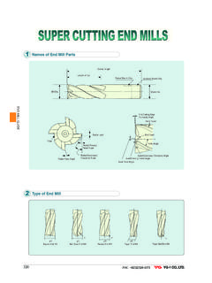
5 Mohan [2] describes profile relieve cutters in Milling contour surfaces Davies [3] describes bonding of carbide inserts to such tools as end-mills instead of brazing them. Milling plays a central role as a shape generating technique in the machining of hollow forms. Such hollow shapes are used in tools for presses, forges, and foundry work. Granger [4] describes the selection of a Milling Cutter in terms of average chip thickness rather than in feed /tooth. This approach depends on a combination of factors including material, component design, and strength, rigidity of fixturing, and type and age of machine. II. CUTTING CONDITIONS IN Milling In Milling , each tooth on a tool removes part of the stock in the form of a chip. The basic interface between tool and work part is shown in This shows only a few teeth of a peripheral Milling Cutter : Modeling and Analysis of a Surface Milling Cutter Using finite Element Analysis 50 Figure1: Milling operation Cutting velocity V is the peripheral speed of the Cutter is defined by V = DN, where D is the Cutter outer diameter and N is the rotational speed of the Cutter .
6 As in the case of turning, cutting speed V is first calculated or selected from appropriate reference sources and then the rotational speed of the Cutter N, which is used to adjust Milling machine controls, is calculated. Cutting speeds are usually in the range of ~4 m/s, lower for difficult-to-cut materials and for rough cuts, and higher for non-ferrous easy-to-cut materials like aluminum and for finishing cuts. Three types of feed in Milling can be identified: [5] feed per tooth, fz: the basic parameter in Milling equivalent to the feed in turning. feed per tooth is selected with regard to the Surface finish and dimensional accuracy required. Feeds per tooth are in the range of ~ mm/tooth, lower feeds are for finishing cuts. feed per revolution, fr: it determines the amount of material cut per one full revolution of the Milling Cutter . feed per revolution is calculated as f r = fzz z=being the number of the Cutter s teeth; feed per minute, fm: feed per minute is calculated taking into account the rotational speed N and number of the Cutter s teeth z, f m = fzzN = frN feed per minute is used to adjust the feed change gears.
7 III. TYPES OF Milling OPERATIONS Owing to the variety of shapes possible and its high production rates, Milling is one of the most versatile and widely used machining operations. The geometric form created by Milling fall into three major groups: Plane surfaces: the Surface is linear in all three dimensions. The simplest and most convenient type of Surface ; Two-dimensional surfaces: the shape of the Surface changes in the direction of two of the axes and is linear along the third axis. Examples include cams; Three-dimensional surfaces: the shape of the Surface changes in all three directions. Examples include die cavities, gas turbine blades, propellers, casting patterns, etc. IV. Milling OF FLAT SURFACES Peripheral Milling : In peripheral Milling , [6] also called plain Milling , the axis of the Cutter is parallel to the Surface being machined, and the operation is performed by cutting edges on the outside periphery of the Cutter .
8 The primary motion is the rotation of the Cutter . The feed is imparted to the work piece. The basic form of peripheral Milling in which the Cutter width extends beyond the work piece on both sides is called slab Milling . Figure 2: Types of Milling Operations (a) Peripheral Slab Milling (b) Face Surface Milling Face Milling : In face Milling , Cutter is perpendicular to the machined Surface . The Cutter axis is vertical, but in the newer CNC machines it often is horizontal. In face Milling , machining is performed by teeth on both the end and periphery of the face- Milling Cutter . Again up and down types of Milling are available, depending on directions of the Cutter rotation and feed . Face Milling is usually applied for rough machining of large surfaces. Surface finish is worse than in peripheral Modeling and Analysis of a Surface Milling Cutter Using finite Element Analysis 51 Milling , and feed marks are inevitable.
9 [7] One advantage of the face Milling is the high production rate because the Cutter diameter is large and as a result the material removal rate is high . Face Milling with large diameter cutters requires significant machine power. Partial face Milling End Milling : In end Milling , the Cutter , called end mill, has a diameter less than the work piece width. The end mill has helical cutting edges carried over onto the cylindrical Cutter Surface .[8] End mills with flat ends (so called squire-end mills) are used to produce pockets, closed or end key slots, etc. In this paper face Milling is considered for Modeling and Analysis purpose. V. finite ELEMENT Analysis OF FACE Milling Cutter In order to perform a finite element Analysis , it is necessary to determine the forces acting on the Cutter . From the given conditions the load (Wt) acting on a single tooth may be represented as: - Equation (1) where H is the power, in kW, n is the speed, in rpm, and D is the diameter of the Cutter .
10 The stress calculation at the tip of the tooth of the Cutter is estimated based on the concept of gear tooth stresses. The stress at each speed is determined by [9]: - Equation (2) The maximum allowable stress at the tip of the Cutter is determined as: -Equation (3) Where as: VI. MATERIAL PROPERTIES high Speed steel is the material chosen for the Milling Cutter and the properties are tabulated in Table 1 Tensile strength (Mpa) 900/1000 Young Modulus E (Mpa) 200000/210000 Compressive Strength(Mpa) 3000/3200 Ductility(compression) % 8/10 Thermal Expansion /0C Thermal Conductivity(W/m k) 17/18 Specific Heat (J/Kg K) 500/540 Table 1: Properties of high speed Steel Milling Cutter VII. MODELLING OF A Milling Cutter Using CATIA The Cutter as per the specifications mentioned above has been modelled in CATIA.