Transcription of Modeling the W6NL 40m Moxon - K3LR Multi / Multi …
1 Modeling the 40m w6nl Moxon 1 April 13, 2012 Modeling the w6nl 40m Moxon greg ordy , W8 WWV April 13, 2012 This note looks at the antenna and antenna model for the 40 meter Moxon Yagi designed by Dave Leeson, w6nl . The performance of the antenna, through the model, will be explored in several typical settings. The antenna is modeled using the EZNEC1 package, built upon the NEC2 engine. Best results are obtained with the NEC-4 engine. Table of Contents Introduction ..2 Model File Included ..2 Tool Antenna Measurements ..3 The Moxon Rectangle ..3 The w6nl Moxon Antenna Model ..5 Stepped Diameter Correction ..7 An Example: 20m 5 Element SWR Comparison ..10 Gain Comparison ..11 Elevation Pattern ..12 Summary ..14 Example Moxon Antenna Performance ..14 Single Moxon at 60 ..15 Single Moxon at 90 ..18 Single Moxon at 120 ..19 Single Moxon at 185 ..20 Moxon Stack, BIP ..21 Moxon Stack, Comparison Across Moxon Examples.
2 24 SWR Gain Comparison ..25 F/B Comparison ..26 1 EZNEC, by Roy Lewallen, W7EL, is available from EZNEC is a registered trademark of Roy W. Lewallen. 2 NEC Numerical Electromagnetics Code. The Wikipedia page contains additional information. Modeling the 40m w6nl Moxon 2 April 13, 2012 Introduction The antenna which is the topic of this note is described in a document titled: w6nl Moxon on Cushcraft XM240. A copy of that document is part of the .zip file that contains this note. The document centers on the construction details and the mechanical conversion of the Cushcraft XM2403 into the w6nl Moxon . I was involved with making some performance measurements of a stack of two w6nl Moxon s. As part of that work, some questions arose and it appeared that a model of the antenna would be illuminating as is most always the case with antennas. Not finding a model immediately available, I used the information in the w6nl document to create a model.
3 Running the model showed that the NEC-2 engine, even with the stepped diameter correction algorithm available (but not used), produced results with differences that could be confusing in trying to evaluate the overall performance of the antenna. Best results were obtained with the NEC-4 engine. This note describes what was discovered along the way, and includes modeled results from several installation scenarios. Model File Included If you have discovered this note as part of a .zip file, you should find the antenna model in the same archive. The file is named It is a single w6nl Moxon located at a height of 60 . By using the EZNEC Wire manipulation commands, it should take very little additional work to change the height and/or create stacks. Before rushing off to run the model, please be sure to read through the rest of this note so that you understand the ramifications of using the NEC-2 engine as opposed to the NEC-4 engine.
4 Tool Flow A few words on the software tool flow used in this note. 3 Modeling the 40m w6nl Moxon 3 April 13, 2012 The models were run using two versions of the EZNEC package. One is EZNEC Pro/2, based upon the NEC-2 engine. For this antenna, using the standard EZNEC or EZNEC+ packages should provide identical results since they all use the NEC-2 engine, and no special Pro features were used. The model I created used 200 segments per antenna. This means that the free version of EZNEC, with a 20 segment limit, cannot be used. The second package is EZNEC Pro/4, which uses the NEC-4 engine. EZNEC Pro/4 results were provided by Dan Maguire, AC6LA. I would like to thank Dan for running the models and contributing his time to this project. Dan has made other contributions to the Moxon quest, and they will be described later. Since an important part of the analysis was looking at band sweeps of antenna characteristics, EZNEC was run in sweep mode, and the resulting data was post processed with the LBDXView package.
5 LBDXView is available on the Internet, and is also included on the CD included with the 5th edition of ON4UN s Low-Band DXing. Antenna Measurements This note focuses on the antenna model and the modeled performance. A companion note will look at some field measurements, and how those compare to modeled results. The Moxon Rectangle The Moxon Rectangle, named after Les Moxon , G6XN (SK), is an interesting and valuable design. In its initial form, it amounts to a two element parasitic (Yagi-Uda) array that has the tips bent at a 90 degree angle towards the other element. One of the things that I ve learned over the years about antennas is that there are usually no free lunches. Most any improvement in one area comes with a cost in another area. The Moxon Rectangle comes close to challenging that principle because it offers a lot of good news without too much bad. Generally speaking, it s viewed to have: 1. Smaller Physical Footprint (due to the bent elements).
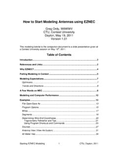
6 2. Good front to back ratio and gain (compared to other 2 element designs). 3. Direct 50 Ohm feed, with relatively wide bandwidth. Modeling the 40m w6nl Moxon 4 April 13, 2012 Figure 1 Moxon Designs The top design in the figure shows the classic 2 element parasitic Yagi, with a driven element (DE) and reflector (REF). The reflector is longer than the driven element, and both are around wavelength long. The initial Moxon , in the middle, shows the tips bent 90 degrees towards the center. The w6nl variation on this design is shown at the bottom. Much has been written about the Moxon and the impact of the bends at the ends of the elements. On the Internet, a good source of information is the Moxon Antenna Project, at: The web page archives of Cebik, W4 RNL (SK) have a number of Moxon related articles ( ). Dan Maguire, AC6LA, has written a Moxon generator program ( ), useful for computing dimensions and even models as a function of frequency.
7 Modeling the 40m w6nl Moxon 5 April 13, 2012 My first practical experience with a Moxon took place over a dozen years ago. I was involved with a Moxon for 80 meters. It was made of wire, and designed to be bidirectional, using relays to load the reflector with inductors and relays to select the fed element. What made that project interesting was that it was located at the top of an apartment building in India (VU). The w6nl Moxon Antenna Model Given a detailed description of the antenna, which was available in this case, creating a model is not hard, but it can be time consuming and tedious. The challenge is getting all of the coordinates correct, as well as the Wire diameters. There are lots of little numbers to get right. I believe the model matches the description. If it does not, all of the errors are due to my poor transcription. Blame me, not the original design. As mentioned earlier, a file containing the model, , is part of the.
8 Zip file containing this note. As is common with upper HF self supporting antennas, the model units are inches, since this is most convenient. If you modify the model, perhaps to change the height, be sure that you are working in inches, not feet. In the actual antenna, the short perpendicular elements are connected to the bottom side of the main elements with brackets and clamps. This is shown in the following diagram taken from the document: Modeling the 40m w6nl Moxon 6 April 13, 2012 Figure 2 Perpendicular Element Construction Details There are four similar junctions on the antenna one on each end of the driven element and the reflector. In the model, I have connected the perpendicular element directly to the main element. In effect, it is attached where the red dot is located on the diagram. So that all Wires meet at ends and do not overlap, the model has a Wire junction at that same point. Except for this detail, you should find a 1 to 1 correspondence between exposed tubing in the construction plans and modeled Wires.
9 I manually specified the number of Wire segments in the model. If you run the model you will find a few segment length warnings. These are due to the very short Wires created where the perpendicular elements attach. EZNEC has an automatic segmentation feature that was not used, but it was tried. It was unable to get rid of the warnings. I don t believe that any harm comes from these warnings. There is one important piece of information not contained in the construction article the spacing between the two elements! That is feet (21 feet, 6 inches). Modeling the 40m w6nl Moxon 7 April 13, 2012 Stepped Diameter Correction Now it s finally time to get into what I believe may be a source of confusion over modeled results for this antenna. A known problem with the NEC-2 engine is its treatment of stepped diameter Wires. This condition is inherent in elements constructed from telescoping aluminum tubing. As the next section of tubing is added, we step down in diameter.
10 This is great for mechanical, weight, and cost considerations, but creates a complexity for the electrical model (remember, no free lunches). One way around this problem is to select a Modeling engine that does not have a problem with stepped diameters. This would include NEC-4 and MININEC. The NEC-2 engine, with the problem, however, is perhaps the most popular Modeling engine in use, being both powerful and free (well, there s one free lunch). Another way around this problem is to discover a single Wire with a constant diameter that is considered to be electrically equivalent to the stepped diameter element. If we model (in NEC-2) the single Wire with the constant diameter in place of the stepped diameter Wires, we have side-stepped the problem. An algorithm to convert a set of stepped diameters wires into a single equivalent wire was presented in the book Physical Design of Yagi Antennas, by Dave Leeson4 (ARRL, 1992) (page 8-18).