Transcription of MODELLING OF GAS TURBINE AND GAS TURBINE EXHAUST …
1 International Journal of Scientific & Engineering Research, Volume 6, Issue 4, April-2015 925 ISSN 2229-5518 IJSER 2015 MODELLING OF GAS TURBINE AND GAS TURBINE EXHAUST AND ITS UTILISATION AS combined cycle IN UTILITY SYSTEM *Saddiq , Perry , Ndagana and Mohammed 1 Department of Chemical Engineering, Modibbo Adama University of Technology Yola 2 Centre for Process Integration, CEAS, The University of Manchester ABSTRACT: Due to increasing demand for energy and unstable and continuous increase in cost of fossil fuel, attention has been shifted from the traditional power plants to energy generation using gas turbines because of the availability and low cost of its fuel. This led to the need for proper understanding of the gas TURBINE performance and how the energy from gas TURBINE can be optimally utilized.
2 Many authors have worked on the modeling of gas TURBINE performance and optimal utilization of its energy output but they rarely consider different gas TURBINE configurations and how the configurations can be integrated into utility system. This work will therefore focus on modeling gas TURBINE and gas TURBINE EXHAUST using Aspen HYSYS, taking into account different possible configurations. The objective is to model different configurations of gas TURBINE maximizing the energy output usage (both power and heat) in a utility system using combined cycle . The results obtained shows that different configuration of gas TURBINE gives better result compared to simple gas TURBINE . The improvement is so prevalent most especially if it is integrated with utility system by generating high pressure steam in heat recovery steam generator to be used in steam TURBINE in form of combined cycle .
3 Better performance of the gas TURBINE in combined cycle is obtained if multiple steam pressure level is generated in the heat recovery steam generator. Keywords: Gas TURBINE , Configuration, MODELLING , EXHAUST Energy, Brayton cycle , combined cycle , Utility System INTRODUCTION Gas TURBINE is a heat engine that converts the heat obtained from fuel by the use of compressed hot gas as a working fluid, into mechanical output power either as torque through a rotat-ing shaft or as jet power in the form of velocity through an ex-haust nozzle [8]. Gas TURBINE can be operated in one of these various ways according to their purpose which include the op-eration for power generation only and for co-generation where it is operated to generate heat and power [5].
4 For its operation for power generation only, much heat is wasted since the tur-bine EXHAUST outlet of the gas TURBINE is always at high tem-perature of about 450 600oC [13]. In this case, it will be dis-covered that the efficiency of the TURBINE is low compared to other operations [9]. Utilising the gas TURBINE EXHAUST will re-duce the heat wasted to the environment which is currently supplying 10% heat and electricity in Europe [16]. For this purpose, there is therefore the need to model the gas TURBINE EXHAUST to determine the amount of heat to be obtained from the EXHAUST and how the EXHAUST heat can be adequately uti-lised. The operation of a gas TURBINE is described by Brayton cycle which is a cycle where both compression and expansion pro-cesses take place in the same rotating machinery [11].
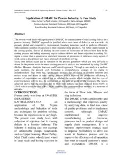
5 The cycle is usually presented in form of open cycle as shown in Figure 1. Brayton cycle is evaluated classically using thermo-dynamic parameters such as temperature, pressure, specific heat, adiabatic compression exponents and efficiency factors where standard conditions are conveniently used for some factors such as 15 oC for ambient temperature, bar for atmospheric pressure and 60% for relative humidity estab-lished by International Standard Organisation (ISO) [3]. In Brayton cycle , air enters the compression chamber and is compressed at constant entropy, fuel is added to it in the com-bustion chamber and burnt at constant pressure, the hot gases then expand in the TURBINE at constant entropy and the expan-sion drives the blade while the remaining heat is rejected to the environment at constant pressure.
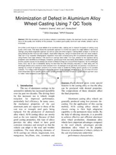
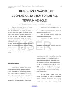
6 It can be presented on either a temperature-entropy (T-S) diagram or pressure-volume (P-V) diagram as shown in Figures 2 and 3 respective-l y. Figure 1: Schematic of a Simple Gas TURBINE IJSERI nternational Journal of Scientific & Engineering Research, Volume 6, Issue 4, April-2015 926 ISSN 2229-5518 IJSER 2015 Gas TURBINE is made up of three major components described as primary modules [7]. The major components are compres-sors, combustion chamber and the TURBINE . Compressors are parts of gas TURBINE that takes in air from the environment and compress it so as to supply it at high pressure to the combus-tion chamber [7]. The compressor is connected to the TURBINE by one or two shafts so that the TURBINE can drive it.
7 About 50 to 60% of the power from the TURBINE is used for operating the compressor [3]. The combustion chamber is where the air from the compressor is mixed with the fuel supplied to the chamber which is in form of a direct fired heater. 25 to 40% of the air entering the combustion chamber at a velocity of about 122 to m/s is used for the combustion process; the remaining is used for cooling and for dilution purpose [7]. For normal op-eration, the air to fuel ratio is between 45:1 and 130:1 and the compressed air is between a temperature of 200 oC and 550 oC due to the compression work done on it which is increased to about 1800 2000 oC by the combustion process. It is then reduced to between 850 oC and 1700 oC as the highest allow-able temperature by either the excess air (about 60% to 75% inflow air) not used for combustion process, and/or steam in-jection.
8 Although the amounts can be calculated from material and energy balances, the amount of excess air is a degree of freedom that cannot be established by thermodynamic rela-tion. Consequently, the starting point for the model is to use the published data for full load performance of commercial gas turbines which mostly depend on the TURBINE inlet temperature as given by [12]. The combustion process is achieved by stoichiometric burning of carbon or hydrogen in oxygen with the release of heat [7]. The TURBINE is a component that drives the compressor and also provides power for use. The hot air enters the TURBINE at the temperature of between 850 oC and 1700 oC with the speed increasing to around 762 m/s in parts of the TURBINE [7]. The efficiency of the TURBINE depends highly on the inlet tem-perature.
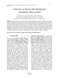
9 It has polytrophic efficiency of between 85% and 95% [6]. The temperature of the EXHAUST coming out from the gas TURBINE is between 360 oC and 610 oC [7]. There are various configurations of gas TURBINE all with the intention of improving the performance of the gas TURBINE . Some common configurations are inlet air cooling, steam in-jection, reheating, regeneration and intercooling [15, 20,17]. Utility system is an important part of most processes. It pro-vides heating, cooling and also power needed by the process. A typical utility system and its interaction with process is pre-sented schematically in Figure 5. In large processes, the cost of fuel and power is very significant which then calls for the need for proper management of the utility system in order to save energy [19].
10 There is therefore the need to model the basic elements of the system among which is a gas TURBINE . Figure 4: Utility System and its Interaction with a Pro-cess [19]. The challenge of constantly enhancing gas TURBINE perfor-mance had drawn a lot of attentions thereby leading to a lot of research. Many works have been done on the MODELLING of gas TURBINE with the intention of determining the performance of the gas TURBINE , integrating the heat of the EXHAUST into a process and/or using it for some heating purposes. The works are though still useful in predicting the behaviour of gas tur-bine and gas TURBINE EXHAUST , they neglect some important factors that have to do with the configuration of the gas tur-bine. The work of [17] estimated the performance of gas tur-bine varying the operating conditions such as the fuel/air ratio, inlet and outlet temperatures and the compressor and TURBINE efficiencies using MATLAB.