Transcription of MODELS J, K, KK, L, LQ, LL AND LM - Viking Pump Canada
1 INTRODUCTION The illustrations used in this manual are for identification purposes only and cannot be used for ordering parts. Obtain a parts list from the factory or a Viking representative. Always give complete name of part, part number and material with model number and serial number of pump when ordering repair parts. The pump model number and serial number are on the nameplate. In the Viking model number system, basic size letters are combined with series number. TECHNICAL SERVICE MANUAL HEAVY-DUTY BRACKET MOUNTED PUMPS SERIES 124 MODELS J, K, KK, L, LQ, LL AND LM Viking PUMP, A Unit of Idex Corporation, 661 Grove Ave.
2 , Windsor, Ontario N9A 6M3 Canada SECTION 3 BULLETIN TSM-124-V ISSUE C-2009 This manual deals only with Series 124 Heavy Duty Bracket Mounted Pumps. Pump specifications and recommendations are listed in Catalog Section 3, series 124 Heavy Duty Bracket Mounted Pumps. CONTENTS Special Information 2 Maintenance 2 Packed Pump Breakdown Drawing 4 Packed Pump Disassembly 5 Packed Pump Assembly 6 Sealed Pump Breakdown Drawing 7 Sealed Pump Disassembly 8 Sealed Pump Assembly 9 Installation of Carbon Graphite Bushings 10 End Clearance
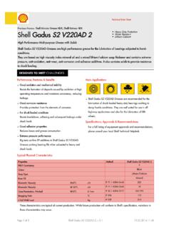
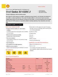
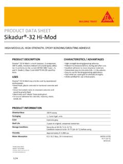
3 Adjustment 10 Pressure Relief Valve Instructions 11 Pneumatic Testing 11 Pressure Adjustment 12 Troubleshooting 13 Pump Inspection Report 14 Notes 15 Warranty 16 KK-124 LL-124 Shown with 180 Deg. Ports LM-124 UNMOUNTED PUMP UNITS J-124 K-124 KK-124 L-124 Units are designated by the unmounted pump model numbers followed by Arrangement indicating drive style.
4 LQ-124 13-Direct Connected LL-124 53-Belt Driven LM-124 70-Commercial Speed Reducer 90-Commercial Gear Motor DANGER BEFORE OPENING ANY Viking PUMP LIQUID CHAMBER (PUMPING CHAMBER, RESERVOIR, RELIEF VALVE ADJUSTING CAP FITTING ETC.) BE SURE: 1. THAT ANY PRESSURE IN CHAMBER HAS BEEN COMPLETELY VENTED THROUGH SUCTION OR DISCHARGE LINES OR OTHER APPROPRIATE OPENINGS OR CONNECTIONS. 2. THAT THE DRIVING MEANS (MOTOR, TURBINE, ENGINE, ETC.) HAS BEEN LOCKED OUT OR MADE NON- OPERATIONAL SO THAT IT CANNOT BE STARTED WHILE WORK IS BEING DONE ON PUMP.
5 3. THAT YOU KNOW WHAT LIQUID THE PUMP HAS BEEN HANDLING AND THE PRECAUTIONS NECESSARY TO SAFELY HANDLE THE LIQUID. OBTAIN A material safety data sheet (MSDS) FOR THE LIQUID TO BE SURE THESE PRECAUTIONS ARE UNDERSTOOD. FAILURE TO FOLLOW ABOVE LISTED PRECAUTIONARY MEASURES MAY RESULT IN SERIOUS INJURY OR DEATH. ROTATION: Rotary gear pumps operate equally well in a clockwise or counterclockwise rotation. The shaft rotation determines which port is suction and which is discharge. Port in area where pumping elements (gear teeth) come out of mesh is suction port. PRESSURE RELIEF VALVES: 1. Viking pumps are positive displacement pumps and must be provided with some sort of pressure protection.
6 This may be a relief valve mounted directly on the pump, an inline pressure relief valve, a torque limiting device or a rupture disk. 2. There are relief valve options available on pump MODELS . Options may include a return to tank relief valve and a jacketed relief valve. Pumps equipped with a jacketed head are not available with a relief valve. 3. If pump rotation is reversed during operation, pressure protection must be provided on both sides of pump. 4. Relief valve bonnet (see page 11) must always point towards suction side of pump. If pump rotation is reversed, remove pressure relief valve and turn end for end. Figures 2 and 3 show 2 possible configurations, both have side suction and top discharge.
7 A right-hand pump turns in the opposite direction to the left-hand pump. 5. Pressure relief valves cannot be used to control pump flow or regulate discharge pressure. SPECIAL INFORMATION SPECIAL MECHANICAL SEALS can be installed either next to rotor hub or behind the bracket bushing. Extra care must be taken in repair of pumps with mechanical seals. Read and follow all special information supplied with pump. MAINTENANCE Series 124 pumps are designed for long, trouble-free service life under a wide variety of application conditions with a minimum of maintenance. The points listed below will help provide long service life. LUBRICATION: All pumps are greased at the factory.
8 External lubrication must be applied slowly with a grease gun to all lubrication fittings every 500 hours of operation with multi - purpose grease . Do not over- grease . Applications involving very high or low temperatures will require other types of lubrication. Consult factory with specific lubrication questions. PACKING ADJUSTMENT: New packed pumps require initial packing adjustment to control leakage as packing runs in . The adjustment should be made while the pump is operating with normal operating pressure on the discharge of the pump. Make adjustments carefully and do not over-tighten packing gland. Evenly tighten the gland fasteners until the leak is reduced to a very slow drip.
9 If over tightened the packing will over heat, score the shaft and reduce life. After initial adjustment, inspect periodically for increased leakage and re-adjust. Once the gland has been tightened to the stuffing box face, loosen the packing gland and add one ring to the stuffing box, then adjust again. Refer to instructions under Disassembly, page 5, and Assembly, page 6, regarding repacking pump. Figure 2, Right Hand Pump Figure 3, Left Hand Pump 2 Figure 4, Idler bushing press fit CLEANING PUMP: Keep pump as clean as possible. This will facilitate inspection, adjustment and repair work and help prevent overlooking a dirt covered grease fitting.
10 STORAGE: If pump is to be stored, or not used for six months or more, pump must be drained and a light coat of lubricant and rust preventative suitable to the application must be applied to all internal pump parts. Lubricate fittings and apply grease to pump shaft extension. Rotating the pump shaft by hand, one complete revolution every 30 days to circulate the oil. SUGGESTED REPAIR TOOLS: The following tools must be available to properly repair Series 124 pumps. These tools are in addition to standard mechanics tools such as open-end wrenches, pliers, screwdrivers, etc. Most of the items can be obtained from an industrial supply house.