Transcription of Modifications for the Dynaco tm MKIII Mono Power Amplifier
1 Modifications for the Dynaco tm MKIII Mono Power Amplifier BASIC FEATURES: The basic modification consists of replacing the driver board, performing easily done minor Modifications revising a few connections to the output tubes, and installing to the Power supply, your choice of input and output connectors. Recommended output stage connection is triode. The design can be as simple or all out as desired. SONICS: Clean open, quick and lucid highs. Lifts the veil of grit and grain found in the stock Amplifier . Detail and depth akin to the best modern Well controlled bass with good extension. Eliminates the sometimes flabby bass of the original Amplifier . Warm, sweet midrange without being euphonic. Much lower distortion, greater perceived bandwidth, and a much more revealing sound than the original. Low feedback design is particularly good for Quad ESL's and other difficult to drive designs. SPECIFICATIONS: * Power output up to 25 watts rms in triode mode and 50 watts in ultralinear mode.
2 * Gain typically greater than +22dB in triode mode, ultra-linear mode +30dB recommended. DESCRIPTION: * A 12AX7A/5751 and 12AU7A/12BH7A are utilized in a self balancing cascade differential Amplifier circuit with headroom to spare. * Compact, requires no modification of existing MKIII chassis sheetmetal. Parts List For A Pair Of MKIII Driver Boards (Just PCB parts): Resistors: 2 X 100 1% Holco Metal Film H4 (RN60 Equivalent) 4 X 221 1% Holco Metal Film H4 4 X 1% Holco Metal Film H4 6 X 1% Holco Metal Film H4 2 X 1% Roederstein Resista 2W min ( Dale RN70C/D) 2 X 1% Holco Metal Film H4 4 X 1% Roederstein Resista RN60 4 X 100K 1% Roederstein Resista RN60 4 X 221K 1% Holco H4 Capacitors: 4 X REL TFT/RTX (can get away with 400V w/TFT only) Alternative might be to use the Cequa from Angela Sockets: 4 X AMP B9A Tubes: 2 X 12AX7 LPS (I highly recommend these in this design.) 2 X 12BH7A GE gray plate or RCA black plate Wire: I strongly recommend Kimber TCSS.
3 ASSEMBLY INSTRUCTIONS - Procedure: 1.) Clip all wiring to the old driver board assembly. Remove driver board, retaining hardware unless replacements are available. 2.) Remove all original wiring connected to pcb including filament wiring, Power , feedback connection, ground connection to the black lead of the output transformer,input, etc. 3.) Remove the old 1K resistors connected between pins 5&6 of the output tube sockets and replace with the new 1K 5% resistors furnished. Remove the old ohm resistor connected to pins 1&8 via a jumper to both tube sockets. Replace with individual 15 ohm resistors connected to ground @ one end and pins 1&8 of each socket respectively. 4.) Remove original phono jack and discard. 5.) Install new board such that the large yellow coupling caps are facing towards the output tubes. The Kennedy Audio logo should face towards your right with the Amplifier chassis upside down. 6.) Install new phono jack.
4 Solder a short wire from the RCA ground lug to the leftmost or ground eyelet, then solder two additional wires, one to the quad cap ground, the other to the black secondary lead of the output transformer. Solder a short wire from the center contact of the RCA to the open eyelet just above and to the right of the ground eyelet. You have just completed the ground and input connections! 7.) Solder a wire from the third eyelet from the left (connected to 1%) to the 16 ohm tap of the output transformer. Now you have completed the feedback connection! 8.) Carefully remove the and 22K resistors located on the quad cap. and replace with (mo) and 100K (mf) respectively. Solder a wire from the junction of the and 100K to the eyelet that is almost exactly in the center of the board. Solder another wire to the end of the quad cap where the other end of the 100K is soldered and solder this to the eyelet on the left second from the top of the board.
5 9.) Carefully remove the selenium rectifier (gray block connected to transformer) and install the furnished terminal strip. Install the 1N4005 at one end of the strip - cathode (banded end) facing the end - solder the red/blk wire from the transformer to the cathode. Solder negative end (-) end of one 330 uF cap to opposite end of the diode, then solder the 470 ohm to this point, solder the other end to another 330 uF cap (-) and solder two wires, one to the end of the bias pot previously connected to the old 1K resistor and the other which will connected in step 12. Solder both positive leads from the electrolytic capacitors to the grounded eyelet, and run a wire back to one of the ground terminals of the quad cap. and solder. This completes the new bias supply. 10.) Solder a wire from the leftmost top eyelet to pin 6 (1K resistor from here to pin 5) of the closest output tube. 11.) Solder a wire from the rightmost top eyelet to pin 6 (1K resistor from here to pin 5) of the adjacent tube socket.
6 12.) Solder a wire from the center top eyelet to the center terminal of the bias pot. Output bias circuit is complete. 13.) Solder the remaining wire from step 9 to the point marked -80V on the pcb. Now - 80V Bias to first differential Amplifier is connected. 14.) Carefully remove and insulate the wire connected to pin 4 of each output tube socket. (6550/KT88) Solder a 330 ohm resistor from pin 3 to pin 4 of each socket. Triode operation implemented. 15.) Twist a pair of wires together and solder one end to pins 2&7 of either output tube socket. Solder the end to the center eyelets of the closest socket on the pcb, then repeat the process from this socket to the other socket on the board. 16.) Carefully recheck all wiring for errors and shorts. Initial Testing 1.) Install a 12AX7A/5751 in the socket closest to the front of the Amplifier , and a 12AU7A/12BH7A in the second socket. Install both 6550's in their sockets, but DO NOT install the 5AR4 yet.
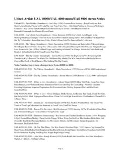
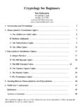
7 2.) Plug in the unit and turn on. Observe to see whether tube filaments are glowing after 30 seconds or 3.) Measure pin 4 of the 5AR4 to determine that approx. 460-490 Vac is present. 4.) Measure bias supply to 12AX7A, it should be roughly -80V. 5.) Check pin 5 of each 6550 to determine that the voltage on both pins is the same, then set bias pot so that you measure -65V on these pins. 6.) Turn unit off and install 5AR4. Turn on and wait several minutes, and then measure from pin 1 of each output tube to ground. Both should be within 10% of each other or tube match is not optimum for best performance. Set bias so voltage at this point is approx. Vdc. Range is .75 V - Vdc. 50mA - 86mA approx per tube. 7.) Enjoy your new Amplifier ! 2000 by KTA Information for obtaining -80V bias, from CVD Failsafe Power supply PCB, for 12AX7 tube in KTA driver circuit ( see full KTA driver schematic on last page). Given below is CVD- Power supply Schematic only.
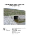
8 Modifying KTA driver board for Failsafe bias connection