Transcription of MODULE 3 Introduction to Internal Combustion Engines
1 MODULE 3 Introduction to Internal Combustion Engines Asst. Prof. Vishnu Sankar Department of Mechanical Engineering Rajagiri School of Engineering & Technology (RSET) = HEAT ENGINE Any engine that converts thermal energy to mechanical work output. Ex: steam engine, steam power plant, jet engine, gas turbine power plant, diesel engine, and gasoline (petrol) engine etc. Asst. Prof. Vishnu Sankar,DME,RSET HEAT ENGINE Internal Combustion (IC) Engine External Combustion Engine On the basis of how thermal energy is being delivered to working fluid of the heat engine, Heat engine can be classified as Asst. Prof. Vishnu Sankar,DME,RSET Internal Combustion engine: Combustion takes place within the working fluid of the engine, Thus fluid gets contaminated with Combustion products. Petrol engine is an example of Internal Combustion engine, where the working fluid is a mixture of air and fuel . External Combustion engine Working fluid gets energy from outside through some heat exchanger (Boiler) Thus the working fluid does not come in contact with Combustion products.
2 Steam engine is an example of external Combustion engine, where the working fluid is steam. Asst. Prof. Vishnu Sankar,DME,RSET Internal Combustion Engines Asst. Prof. Vishnu Sankar,DME,RSET EXTERNAL Combustion Engines Asst. Prof. Vishnu Sankar,DME,RSET Internal Combustion Engines Spark Ignition Engines (ex. Gasoline/Petrol Engine) Compression Ignition Engines (ex. Diesel Engine) Asst. Prof. Vishnu Sankar,DME,RSET Spark ignition engine (SI engine) An engine in which the Combustion process in each cycle is started by use of an external spark. Compression ignition engine (CI engine) An engine in which the Combustion process starts when the air-fuel mixture self ignites due to high temperature in the Combustion chamber caused by high compression. [Spark ignition and Compression Ignition engine operate on either a four stroke cycle or a two stroke cycle] Asst. Prof. Vishnu Sankar,DME,RSET IC Engine components Asst. Prof. Vishnu Sankar,DME,RSET Asst.
3 Prof. Vishnu Sankar,DME,RSET I C Engine Components Block : Body of the engine containing cylinders, made of cast iron or aluminium. Cylinder : The circular cylinders in the engine block in which the pistons reciprocate back and forth. Head : The piece which closes the end of the cylinders, usually containing part of the clearance volume of the Combustion chamber. Combustion chamber: The end of the cylinder between the head and the piston face where Combustion occurs. The size of Combustion chamber continuously changes from minimum volume when the piston is at TDC to a maximum volume when the piston at BDC. Asst. Prof. Vishnu Sankar,DME,RSET Crankshaft : Rotating shaft through which engine work output is supplied to external systems. The crankshaft is connected to the engine block with the main bearings. It is rotated by the reciprocating pistons through the connecting rods connected to the crankshaft, offset from the axis of rotation. This offset is sometimes called crank throw or crank radius.
4 Connecting rod : Rod connecting the piston with the rotating crankshaft, usually made of steel or alloy forging in most Engines but may be aluminum in some small Engines . piston rings: Metal rings that fit into circumferential grooves around the piston and form a sliding surface against the cylinder walls. Asst. Prof. Vishnu Sankar,DME,RSET Camshaft : Rotating shaft used to push open valves at the proper time in the engine cycle, either directly or through mechanical or hydraulic linkage (push rods, rocker arms, tappets) . Crankcase : Part of the engine block surrounding the crankshaft. In many Engines the oil pan makes up part of the crankcase housing. Exhaust manifold : Piping system which carries exhaust gases away from the engine cylinders, usually made of cast iron . Asst. Prof. Vishnu Sankar,DME,RSET Intake manifold :Piping system which delivers incoming air to the cylinders, usually made of cast metal, plastic, or composite material. In most SI Engines , fuel is added to the air in the intake manifold system either by fuel injectors or with a carburetor.
5 The individual pipe to a single cylinder is called runner. Spark plug : Electrical device used to initiate Combustion in an SI engine by creating high voltage discharge across an electrode gap. Asst. Prof. Vishnu Sankar,DME,RSET Flywheel : Rotating mass with a large moment of inertia connected to the crank shaft of the engine. The purpose of the flywheel is to store energy and furnish large angular momentum that keeps the engine rotating between power strokes and smooths out engine operation. Fuel injector : A pressurized nozzle that sprays fuel into the incoming air (SI Engines )or into the cylinder (CI Engines ). Fuel pump : Electrically or mechanically driven pump to supply fuel from the fuel tank (reservoir) to the engine. Asst. Prof. Vishnu Sankar,DME,RSET Asst. Prof. Vishnu Sankar,DME,RSET IC Engines Ignition System SI CI Working Cycle Otto Cycle Diesel Cycle Brayton Cycle No. of Strokes Four Stroke Two Stroke Application Stationary Mobile Cooling System Air Cooled Liquid Cooled No.
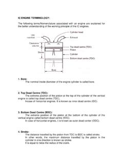
6 Of Cylinders Single Cyl Multi Cyl Cylinder Arrangement Inline Vertical / Straight Horizontal / Flat V, W, H, U, X etc. Radial Opposed Vertical / Straight Horizontal / Flat Asst. Prof. Vishnu Sankar,DME,RSET Bugatti W 16 Subaru H6 Asst. Prof. Vishnu Sankar,DME,RSET Four stroke cycle : It has four piston strokes over two revolutions for each cycle. Two stroke cycle : It has two piston strokes over one revolution for each cycle. We will be dealing with Spark Ignition engine and Compression Ignition engine operating on a four stroke cycle. Asst. Prof. Vishnu Sankar,DME,RSET Figure3 : Engine Terminology Asst. Prof. Vishnu Sankar,DME,RSET Figure 3, shows the pressure volume diagram of ideal engine cycle along with engine terminology as follows: Top Dead Center (TDC): Position of the piston when it stops at the furthest point away from the crankshaft. Top because this position is at the top of the Engines (not always), and dead because the piston stops as this point.
7 Because in some Engines TDC is not at the top of the Engines ( : horizontally opposed Engines , radial Engines ,etc,.) Some sources call this position Head End Dead Center (HEDC). Some source call this point TOP Center (TC). When the piston is at TDC, the volume in the cylinder is a minimum called the clearance volume. Engine Terminology : Asst. Prof. Vishnu Sankar,DME,RSET Bottom Dead Center (BDC): Position of the piston when it stops at the point closest to the crankshaft. Some sources call this Crank End Dead Center (CEDC) because it is not always at the bottom of the source call this point Bottom Center (BC). Stroke : Distance traveled by the piston from one extreme position to the other : TDC to BDC or BDC to TDC. Bore :It is defined as cylinder diameter or piston face diameter; piston face diameter is same as cylinder diameter( minus small clearance). Swept volume/Displacement volume : Volume displaced by the piston as it travels through one stroke.
8 Swept volume is defined as stroke times bore. Displacement can be given for one cylinder or entire engine (one cylinder times number of cylinders). Asst. Prof. Vishnu Sankar,DME,RSET Clearance volume : It is the minimum volume of the cylinder available for the charge (air or air fuel mixture) when the piston reaches at its outermost point (top dead center or outer dead center) during compression stroke of the cycle. Minimum volume of Combustion chamber with piston at TDC. Compression ratio : The ratio of total volume to clearance volume of the cylinder is the compression ratio of the engine. Typically compression ratio for SI Engines varies form 8 to 12 and for CI Engines it varies from 12 to 24 Asst. Prof. Vishnu Sankar,DME,RSET SI Engine Ideal Otto Cycle We will be dealing with four stroke SI engine, the following figure shows the PV diagram of Ideal Otto cycle. Asst. Prof. Vishnu Sankar,DME,RSET Asst. Prof. Vishnu Sankar,DME,RSET Asst. Prof.
9 Vishnu Sankar,DME,RSET Asst. Prof. Vishnu Sankar,DME,RSET Figure4: Suction stroke Asst. Prof. Vishnu Sankar,DME,RSET Four strokes of SI Engine Cycle : Suction/Intake stroke: Intake of air fuel mixture in cylinder through intake manifold. The piston travel from TDC to BDC with the intake valve open and exhaust valve closed. This creates an increasing volume in the Combustion chamber, which in turns creates a vacuum. The resulting pressure differential through the intake system from atmospheric pressure on the outside to the vacuum on the inside causes air to be pushed into the cylinder. As the air passes through the intake system fuel is added to it in the desired amount by means of fuel injectors or a carburettor. Asst. Prof. Vishnu Sankar,DME,RSET Figure5: Compression Stroke Asst. Prof. Vishnu Sankar,DME,RSET Compression stroke: When the piston reaches BDC, the intake valve closes and the piston travels back to TDC with all valves closed. This compresses air fuel mixture, raising both the pressure and temperature in the cylinder.
10 Near the end of the compression stroke the spark plug is fired and the Combustion is initiated. Asst. Prof. Vishnu Sankar,DME,RSET Combustion of the air-fuel mixture occurs in a very short but finite length of time with the piston near TDC ( , nearly constant volume Combustion ). It starts near the end of the compression stroke slightly before TDC and lasts into the power stroke slightly after TDC. Combustion changes the composition of the gas mixture to that of exhaust products and increases the temperature in the cylinder to a high value. This in turn increases the pressure in the cylinder to a high value. Asst. Prof. Vishnu Sankar,DME,RSET Figure6: Combustion followed by Expansion stroke. Asst. Prof. Vishnu Sankar,DME,RSET Expansion stroke/Power stroke : With all valves closed the high pressure created by the Combustion process pushes the piston away from the TDC. This is the stroke which produces work output of the engine cycle. As the piston travels from TDC to BDC, cylinder volume is increased, causing pressure and temperature to drop.