Transcription of Monomer Recovery in Polyolefin Plants Using Membranes - An ...
1 Monomer Recovery in Polyolefin Plants Using Membranes - An UpdateByMarc JacobsDoug GottschlichFrank BuehnerMembrane Technology & Research, Willow RoadMenlo Park, CA Presentation at the1999 Petrochemical World ReviewDeWitt & Company IncorporatedHouston, TexasMarch 23 - 25, 1999 IntroductionDue to the high cost of raw materials, efficient use of chemical feedstocks is a majorconcern in Polyolefin manufacturing. For example, Monomer losses from Polyolefin plant ventstreams typically range from 1 to 2 percent of the total plant feedstock. With 300 polyolefinplants worldwide, and total capacity in excess of 60 million tons per year, worldwide monomerlosses are costing the industry nearly one-half billion dollars per year.
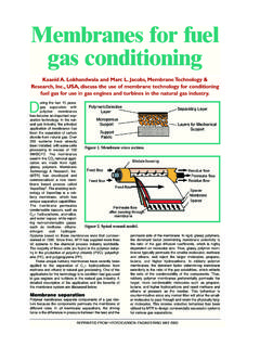
2 There are three sections in the Polyolefin production process where monomers aretypically lost. These three sections are raw material purification, chemical reaction, and productpurification and finishing. All three sections provide significant opportunities for more efficientmonomer use. A schematic of the process is shown in Figure 1 membrane Technology and Research, Inc. (MTR) has developed a membrane -basedprocess to separate and recover hydrocarbons, including propylene and ethylene, from nitrogenand light gases in Polyolefin plant vents. The process, called VaporSep , uses a membrane thatselectively permeates hydrocarbon vapors compared to nitrogen and other light gases.
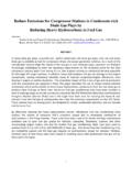
3 Thispaper describes how VaporSep is applied to Polyolefin vent streams to recover valuablemonomers. Examples will be provided from each of the three process Production Process(Polypropylene, HDPE, LLDPE, LDPE)NitrogenVent to flare(N2, C4, C3, C2)Monomersupply andpurificationMonomersupply andpurificationOther rawmaterialssupply andpurificationOther rawmaterialssupply andpurificationPolymerizationreactorPoly merizationreactorExtrusion/pelletingExtr usion/pelletingResindegassingResindegass ingDistillation columnoverhead to flare(N2, C3, C2)Reactor purgeto flare(N2, H2, C4, C2)The membrane is a high flux, thin film composite type that is 10 to 100 times morepermeable to hydrocarbons than to nitrogen.
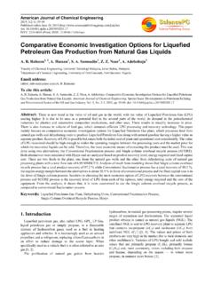
4 The membrane shown in Figure 2, consists of threelayers; a non-woven fabric which serves as the membrane substrate, a solvent-resistantmicroporous support layer for mechanical strength, and a defect-free selective layer whichperforms the 2 The membrane is manufactured as flat sheet and packaged into a spiral-wound moduleas shown in Figure 3. The feed gas enters the module and flows between the membrane on the feed and permeate side of the membrane sheets create flow channels. Thehydrocarbon vapor preferentially passes through the membrane and spirals inward to a centralpermeates collection pipe. Nitrogen and other light gases are rejected by the membrane and exitas Spiral Wound ModuleFigure 3 MTR Multilayer Composite membrane Selective Layer Microporous Layer Support WebApplication of VaporSep in the Raw Material Purification SectionPurification of raw materials is the first step in the Polyolefin process.
5 This step is verycommon because raw materials are not always available at the required purities. In addition, theyhave the capability to use low quality feedstocks which provide greater operating flexibility andlower operating costs. Ethylene supply and purity are very important aspects of polyethyleneproduction. At polymer Plants where an olefin plant is on-site, ethylene purification isaccomplished in an ethylene-ethane splitter column within the olefin process train. However,many polyethylene Plants are stand-alone and purchase feedstocks from refineries or othersources by pipeline. For stand-alone Plants , purification of the feedstocks is achieved in aseparate C2 splitter column.
6 When nitrogen and other light gases (hydrogen and methane) arepresent in the feed, they build up in the overhead of the column and must be vented. This ventstream also contains a significant amount of ethylene, which in a typical plant is valued at morethan $500,000 VaporSep system is shown in Figure 4. The objective of the unit is to remove a fixedamount of the lights and to recycle the enriched ethylene back into the column. Since the streamis at 300 Psig, no feed compressor is required. The vent from the overhead condenser of thecolumn is fed to the membrane . The membrane separates the feed into an ethylene enrichedpermeate and an ethylene depleted residue.
7 The permeate is sent to an existing compressor andthen recycled back to the column while the residue is sent to the flare or fuel. The performance issummarized in Table 4 column overhead Recovery C2-depleted streamC2 Splitter 30% C2 in N2, H2, CH4 MembraneC2stream Olefin product Heavy Monomer Feed Existing Compressor (light compounds) overhead -enrichedOne unit for this application has recently been commissioned and two additional units areunder active consideration. Opportunities for raw material purification are also found inpolypropylene Plants as well. The application is very similar, except that propylene is thevented Monomer instead of I - System PerformanceRaw Material PurificationFeed Composition (mole %)HydrogenNitrogenMethaneEthylene1822303 0 Ethylene Recovered (#/hr)290 Value of Recovered Ethylene ($000/yr)*370 Capital Cost ($000)200* Ethylene Valued at $300/tonApplication of VaporSep in the Reaction SectionIn a large number of reaction processes, only a fraction of the feed reacts during a singlepass through the reactor to form the desired product.
8 After separation from the product, theunreacted feedstock is recycled back to the reactor. In this recycle process, contaminants build-up to unacceptable levels over time and must be purged. Unfortunately, in addition to thecontaminants, unreacted Monomer is also lost in the purge. By applying VaporSep in thereaction section of the process, 90% of the reactant lost in the purge can be recovered. In the production of Linear Low Density Polyethylene (LLDPE) or High DensityPolyethylene (HDPE), nitrogen is added to the reactor to control the partial pressure of nitrogen is later purged from the reactor, taking a substantial quantity of ethylene and otherco-monomers with it.
9 This stream is normally sent to flare, resulting in Monomer losses in excessof $500,000 per simplified flow diagram of this application is shown in Figure 5. One unit for thisapplication has been in service for two years, two additional units have been in operation fortwelve months, and a fourth unit was commissioned six months ago. The objective of theVaporSep unit is to remove a fixed amount of nitrogen and to recycle the enriched hydrocarbonsback to the reactor. Since the feed stream is at 300 Psig, no feed compressor is required. Thevent from the reactor is initially fed to a heat exchanger to cool the stream and to condense anyhigher boiling hydrocarbons.
10 After the exchanger, the membrane separates the feed into ahydrocarbon enriched permeate stream and a hydrocarbon depleted residue stream. Thepermeate is sent to an existing compressor for recycle back into the reactor while the residue issent to the flare. The performance is summarized in Table II 5 Table II - System PerformanceReaction Section - LLDPE/HDPEFeed Composition (#/hr)HydrogenNitrogenEthyleneEthane1-Bu teneTotal51723287288800 Hydrocarbons Recovered (#/hr)Ethylene1-Butene290284 Hydrocarbon Recovery (%)Ethylene1-Butene8898 Value of Recovered HC* ($000/yr)700 Capital Cost ($000)300*Ethylene and Butene valued at $300/tonReactor Purge Recovery Ethylene-depleted Stream Polymerization Reactor Recycle Gas.