Transcription of Morse Sleevloc Series 2000/3000 Spherical Roller Bearing ...
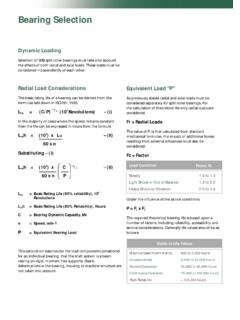
1 SLEEVELOC Installation InstructionsSERIES 2000 / 3000 Spherical Roller Bearing These instructions cover the installation and re-lubri-cation of sealmaster Sleevloc type Spherical rollerbearings. It is important that they be read in their en-tirety before attempting installation or removal. Theprocedures indicated should be carefully to do so can result in mis-installation whichcould cause Bearing performance problems as wellas serious personal AND EXPANSIONBEARING TYPESIn most applications where two or more bearings areused on the same shaft, one Bearing should be of thenon-expansion type to fix the shaft, while the otherbearing should be of the expansion type to allow formounting variables and normal expansion (heat growth)of the shaft.
2 Ideally, the expansion Bearing should belocated on the shaft end furthest from a belt or chaindrive. Two non-expansion bearings may be used onshort shaft applications if the shaft growth (shaft tem-perature change) is minimal. For long shafts and ex-tensive temperature changes, consult sealmaster en-gineers*.Note: The Bearing part number indicates whether theunit is an expansion or non-expansion : SPB2207-C2non-expansionESPB2207-C2E - expansionINSTALLATIONThis is a unit assembly. No attemptshould be made to disassemblethe unit prior to installation. The mounting set screwsmust under no condition be tightened unless theunit is mounted on a shaft since this may damagethe unit. Read through all instructions carefully beforemounting or : The mounting side of the unit is marked MOUNTING.
3 AREA - Clean and organize Bearing instal-lation area, keep well lit. Be sure mountingsurfaces are clean and SHAFT - Shaft should be within tolerancerange shown in Table #1, clean and free of nicksand burrs. Mount bearings on unused section ofshafting or repair/replace shafting as required. Lu-bricate the shaft with light SUPPORT SURFACE - Make sure the baseof the housing and the support surface are cleanand free from burrs. If the housing elevation is ad-justed with shims these must cover the entire con-tact area between the housing and the sup-port UNIT - Slide the unit on the shaftwith the mounting side (marked MOUNTING ) fac-ing outward. If it is difficult to mount Bearing on shaft,do not hammer on any component of the bear-ing.
4 Use a piece of emery cloth to reduce any highspots on shaft. Fit the housing attachment bolts inthe feet but do not tighten. Leave 1 1/2 minimumspacing behind pillow blocks if the dis-mounting screws are to be TIGHTEN SCREWS -Do not use auxiliaryequipment such as a hammeror a pipe when tightening Using the hex key provided, snug all Tighten all set screws, following the patternshown in Table 2, until the long end of the hexkey deflects about 2 1/2 Repeat step 2 to ensure the set screws aretightened INSERT - The expansion unit must becentered in the housing to allow axial shaft expan-sion. Move the Bearing as far as it will go in bothdirections in the housing and determine the cen-tered position. It may be necessary to unload thebearing while moving the HOUSING ALIGNMENT - The maximumpermissible misalignment of the shaft is.
5 Tocheck for alignment, observe the clearance betweenthe sealing shield and the housing or clearance should be evenly distributed aroundthe BOLTS - Tighten the housing attachmentbolts to final tightening careful not to strike any of thecomponents other than the shaftend. Doing so may result in internal Bearing damageor fracture of one or more of the Bearing BLOCKS1. Make sure the exposed shaft extension is freefrom rust and Loosen the housing attachment bolts on one of thetwo Bearing units on the Switch location to the other Bearing on the the small installation hex screws on the sidemarked MOUNTING , 3-4 Strike the end of the shaft (where the loosened hexscrew Bearing is) with a sharp blow. This should freethe Bearing Remove the housing attachment bolts andslide the unit off the Switch location.
6 Loosen the small hex installation(MOUNTING SIDE) set screws 3-4 turns and tightenthe housing attachment Repeat the sharp blow to the end of the UNITS1. Make sure the shaft extension is free from rustand Loosen the housing attachment bolts on one Switch location to the other Bearing on the the housing attachment bolts and smallhex installation set Pull the Bearing housing away from the mountingsurface until the Bearing Switch location. Loosen the small hex installationset Strike the end of the shaft with a sharp blow. Thisshould free the Bearing Remove the housing attachment bolts and slide theunit off the DISMOUNTING SCREWSNote: This procedure will only work with units wherethe dismounting screws are accessible, namely pillowblocks and steps 1-3 as Using a screw driver or other suitable tool, removethe 2 plastic protection Alternately tighten the dismounting hex set screwsin 1/4 turn increments until the Bearing is releasedfrom the Loosen the dismounting hex set screws, unboltthe unit and #1 TABLE #2 Three BoltFour BoltFive BoltTIGHTENING PATTERNSCAUTION Emerson Power Transmission Manufacturing, 1999, 2000 .
7 All Rights Reserved.* sealmaster Engineering Department: Phone : to observe safety precautions could cause personal injury or equipment Installation InstructionsSERIES 2000 / 3000 Spherical Roller Bearing RELUBRICATION INSTRUCTIONSSEALMASTER Sleevloc Bearing units are delivered with a high qualityNLGI 2 lithium soap grease with an EP additive. The Bearing is ready foruse with no (initial) additional lubrication good quality lithium or lithium complex base grease, using mineral oil,conforming to NLGI grade 2 consistency, and an oil viscosity of 455-1135 SUS at 100 F (100-250 cSt at 40 C) may be used for CAREFULLYC ompatibility of grease is critical, therefore consult with SEALMASTERA pplication Engineering and your grease supplier for current grease speci-fications to insure greases are sealmaster bearings are supplied with grease fittingsor zerks for ease of lubrication with hand or automatic grease guns.
8 Alwayswipe the fitting and grease nozzle 784103 REV. 2PS-740-00221/14/00 Printed in Emerson Power Transmission Manufacturing, 1999. All Rights Power TransmissionAurora, IL 60507 Phone: 630-898-9620 TABLE #3 TABLE #4* sealmaster Engineering Department: Phone : lubrication is 521otF 02-F 051otF 02-F 012otF 02-naelCnaelCnaelCshtnoM6shtnoM2skeeW2mu mixaMot0051gnitaRgolataCF 051otpUF 051revOF 052otpUF 052otpUytriDytriD*ytriDyreV*snoitidnoCem ertxEhtnom1otkeew1keew1otyliaDkeew1otyli aDkeew1otyliaDNOITACIRBULERROFEGRAHCESAE RG)sehcni(eziStfahS)secnuo(egrahCesaerG6 1/7161/111ot2/112ot4/3161/32ot22/12ot4/1 23ot61/1122/13ot61/334ot61 safety, stop rotating equipment. Add one half the recommended amountshown in Table #4. Start Bearing and run for a few minutes.
9 Stop bearingand add the second half of the recommended amount. A temperature rise,sometimes 30 F (1 C), after relubrication is normal. Bearing should oper-ate at temperatures less than 200 F (94 C) and should not exceed 225 F(107 C) for intermittent operation. For a relubrication schedule see Table#3. For any applications that are not in the ranges of the table contactSEALMASTER Application to observe saftey precautions could cause personal injury or equipment : The tables below state general lubrication recommendations based on our experience and are intended as suggested or starting points only. Forbest results, specific applications should be monitored regularly and lubrication intervals and amounts adjusted accordingly.