Transcription of MP900 and MP9000 Series Kool-Pak Power Film …
1 2003-2017 Caddock Electronics, and Applications Engineering17271 North Umpqua , Oregon 97470-9422 Phone: (541) 496-0700 Fax: (541) 496-0408e-mail: web: Caddock Distributors listed by country see , MP900 and MP9000 Series Kool-Pak Power film Resistors TO-126, TO-220 and TO-247 Style 15 Watts at +25 C Case Temperature, derated to zero at +150 Ceramic Heat Dissipating Mounting Range of ohm to 1 your thermal design experience with Power semiconductors in TO-126, TO-220, and TO-247 style Power packages to help you get the most out of this unique family of Power resistors. The thermal design issues are the same where Power handling capability is based on the case temperature which is maintained in your design. MP915 TO-126 Style Power PackageUp to 30 Watts at +25 C Case Temperature, derated to zero at +150 Ceramic Heat Dissipating Mounting Range of ohm to 100 Design.
2 MP916, MP925, and MP930 TO-220 Style Power Package100 Watts at +25 C Case Temperature, derated to zero at +175 Ceramic Heat Dissipating Mounting Range of ohm to 100 Design. MP9100 TO-247 Style Power PackageLow Cost Heat Sink Mountable Design featuring an Exposed Ceramic Heat Dissipating Mounting Surface The MP900 and MP9000 Series Kool-Pak Power film Resistors are constructed with Caddock's Micronox resistance film fired onto a flat ceramic substrate. The terminal attachment and resistance element geometry are configured to provide outstanding non-inductive performance. The ceramic substrate is positioned in the molded package such that the resistor element and terminal attachment areas on the substrate are encapsulated in the molded body with the other side of the ceramic being exposed flush with the back mounting surface of the device.
3 This construction is covered by one or more issued patents, also patents custom resistance values and tolerances contact applications of MP900 and MP9000 5% 5% 5% 5% 5% 100 120 150 200 250 300 330 400 470 500 560 750 KMP915, MP925, and MP930 Standard Resistance Values:Tolerance MP915, MP925, and MP930 1% Standard - except as noted. (5% and 20% are available for most resistance values). MP9100 Standard Resistance Values:Tolerance MP9100 1% Standard. 100 Ordering Information: MP915 - - 1%Model Number:Resistor K100 5% 5% MP916 Standard Resistance Values:Tolerance MP916 5% Standard (20% is available).
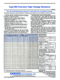
4 Packaging: MP915, MP916, MP925, MP930 resistors are packaged in plastic shipping tubes, 50 pieces per tube. These resistors are available in a 50 piece minimum quantity and in full tube quantity increments ( 50, 100, 150, etc.). The MP9100 resistors are packaged in plastic shipping tubes, 25 pieces per Resistor with Exposed Ceramic Heat DissipatingMounting 1 of 2 2003-2017 Caddock Electronics, and Applications Engineering17271 North Umpqua , Oregon 97470-9422 Phone: (541) 496-0700 Fax: (541) 496-0408e-mail: web: Caddock Distributors listed by country see , RATING, %8060150AB25A - MP915, MP916, MP925, MP930 Max. Temperature, TMax = 150 CB - MP9100 Max. Temperature, TMax = 175 CCASE TEMPERATURE, CDIMENSIONS IN INCHES AND (MILLIMETERS) Figure 3 TO-247 StyleMP9100 All Power and associated overload ratings are derated based upon case temperature using the derating curve.
5 The case temperature is measured at the center of the ceramic mounting surface, with the part properly mounted and under electrical load. Without a heat sink, when in free air at +25 C, the MP915 is rated for watts, the MP916, MP925, MP930 are rated for watts, and the MP9100 is rated for thermal design should satisfy the following equation:Case Temperature (Tc) + [Thermal Resistance (R JC) x Power applied (Watts)] TMAX considering the full operating temperature range of the Note: Mount on a smooth, clean, and flat heat sink surface with a thermal interface material, such as thermal grease. The entire exposed ceramic portion must be in thermal contact with the heat sink. When screw mounting, use a compression washer which provides a mounting force of 150 to 300 pounds (665 to 1330 N).
6 This will provide sufficient pressure on the package over time and through large temperature varia-tions to maintain the maximum Power dissipation capability. Mounting torque to avoid package damage is 8 in-lbs. ( N-m). If a spring clip is used, a clip force of 8 to 30 pounds (35 to 130 N) is recommended to be applied to the center of the package. The clip should be round or smooth in the contact area to avoid concen-trating the load on a small point of the plastic body of the package. Another mounting option is to use a pressure bar method which can achieve a greater mounting force with a greater contact additional applications information regarding mounting and pulse handling see the Caddock Applications Notes at or contact Applications CurveSpecifications:Temperature Coefficient for MP915, MP916, MP925, and MP930:TC referenced to +25 C, R taken at +150 ohms and above, -20 to +80 ppm/ ohm to ohms, 0 to +200 ppm/ ohm to ohm, 0 to +300 ppm/ ohm to ohm, 0 to +500 ppm/ CTemperature Coefficient for MP9100:TC referenced to +25 C, R taken at +175 ohms and above, -20 to +80 ppm/ ohm to ohms, 0 to +150 ppm/ COperating Temperature: -55 C to TMAXI nductance: MP915, MP916, MP925, and MP930 10nH typical.
7 MP9100, 20nH typical, in Series when measured at a point inches from the resistor : The dielectric strength rating of 1500 VrmsAC is based upon connections made between terminals shorted, and the metal surface the part is mounted to or a metal clip in contact with the top surface of the Resistance: 10,000 Megohms resistor element is electrically isolated from the mounting Stability: 2,000 hours at rated Power . R ( percent + ohm) max. Power rating dependent upon case temperature. See derating curve. Momentary Overload: times rated Power with applied voltage not to exceed times maximum continuous operating voltage for 5 seconds. R ( percent + ohm) Resistance: Mil-Std-202, Method 106. R ( percent + ohm) Shock: Mil-Std-202, Method 107, Cond.
8 F. R ( percent + ohm) : 100G, Mil-Std-202, Method 213, Cond. I. R ( percent + ohm) , High Frequency: Mil-Std-202, Method 204, Cond. D. R ( percent + ohm) Strength: Mil-Std-202, Method 211, Cond. A (Pull Test) 5 lbs. R ( percent + ohm) Material: SolderableMeasurement Note: For these specifications, resistance measurement shall be made at a point inch ( mm) from the resistor body.+.030 .004(.76 .10).025 .004 (.64 .10).200 .010( .26) .450 .050( ).115 .010( .26) 1%.110 .010( .26).053 .007( .18).058 .007 ( .18).320 .010( .26).094 .004( .10) .010( .26).080 .020( .51) .640 .010( .26).030 .004(.76 .10).025 .004 (.64 .10) .200 .010( .26) .500 .050( ) .130 .030(.)
9 76) .125 .010( .26) .410 .010( .26) .125 .010( .26) .125 .004( .10) .007( .18).070 .010 ( .26) StyleTO-220 StylePackageTO-220 StyleTO-126 K16 Watts*15 Watts*PowerRating30 Watts*25 Watts* ResistanceR JC film (J) to Case (C) C/Watt150 CFigure 2 Figure 1 DimensionsFigure 2 Figure 2 Max. Temp. T MAX 150 C150 C150 CMP9100TO-247 100 100 Watts* C/WattFigure 3175 CPowerLimitedCeramic mounting surfaceCeramic mounting surfaceCeramic mounting surfaceCeramic mounting surfaceCeramic mounting surfaceFigure 1TO-126 StyleMP915 Figure 2 TO-220 StyleMP916, MP925 and ( ) ( ) ( ) ( ) ( ) ( ) ( ) ( ) ( ) ( ) ( )CLMP + / ( + / )* Derating Using Case Temperature (TC):Page 2 of 2