Transcription of MS-5UD(E)/MS-10UD(E) Series - Fire-Lite
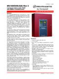
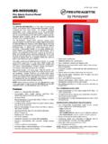
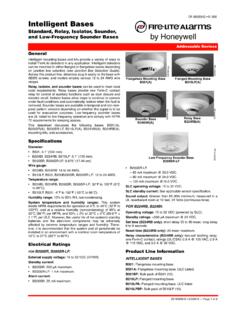
1 DF-52416:D 07/26/2010 Page 1 of 4MS-5UD(E)/MS-10UD(E) SeriesFive Zone Fire Alarm Control Panel Ten Zone Fire Alarm Control PanelControl/CommunicatorsDF-52416:D MS-5UD-3(E) is a five-zone FACP (Fire Alarm ControlPanel) and the MS-10UD-7(E) is a ten-zone FACP. These con-trol panels provide reliable fire signaling protection for small tomedium-sized commercial, industrial, and institutional build-ings. Both panels include built-in communicators for CentralStation Service and remote upload/download. Each of these FACPs is compatible with System Sensor smicroprocessor-based i3 Series detectors. These conventionalsmoke detectors can transmit a maintenance trouble signal tothe FACP indicating the need for cleaning and a supervisory freeze signal when the ambient temperature falls below thedetector rating. Additionally, both the MS-5UD-3 and MS-10UD-7 are compatible with conventional input devices suchas two- and four-wire smoke detectors, pull stations, waterflowdevices, tamper switches, and other normally-open contactdevices.
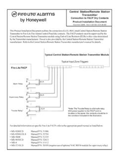
2 Refer to the Fire Lite Device Compatibility Documentfor a complete listing of compatible include four NACs (Notification Appliance Circuits),three programmable Form-C relays (factory programmed forAlarm, Trouble, and Supervisory) and 24 VDC special applica-tion resettable and nonresettable power outputs. The FACP ssupervise all wiring, AC voltage, battery level and telephoneline of a compatible smoke detector or any normally-open fire alarm initiating device will activate audible and visualsignaling devices, illuminate an indicating LED, sound thepiezo sounder at the FACP, activate the communicator andFACP alarm relay, and operate an optional module used tonotify a remote station or initiate an auxiliary control options include a UL listed printer, PRN-6F and FireLite sIPDACT Internet Monitoring module. The FireWatch Seriesinternet monitoring modules IPDACT-2 and IPDACT-2UD per-mit monitoring of alarm signals over the Internet saving themonthly cost of two telephone lines.
3 Although not required, thesecondary telephone line may be retained providing backupcommunication over the public switched telephone line. NOTE: The MS-5UD-3E and MS-10UD-7E offers the same fea-tures as the MS-5UD-3 and MS-10UD-7 but allow connection to240 VAC. Unless otherwise specified, the information in this datasheet applies to both the 120 VAC and the 240 VAC versions ofthese panels. NOTE: For ULC-listed models, see Listed to UL Standard 864, 9th edition. Built-in DACT (Digital Alarm Communicator/Transmitter). Style B (Class B) IDC (Initiating Device Circuit) MS-5UD-3 - five IDCs. MS-10UD-7 - ten IDCs. Style Y (Class B) NAC (Notification Appliance Circuit) - spe-cial application power MS-5UD-3 - four NACs. MS-10UD-7 - four NACs. Notification Appliances may be programmed as Silence Inhibit. Auto-Silence. Strobe Synchronization for System Sensor, Wheelock,Gentex, Faraday, or Amseco devices.
4 Selective Silence (horn-strobe mute). Temporal or Steady Signal. Silenceable or Nonsilenceable. Optional CAC-5X Style Z (Class A) Converter Module forNACs and IDCs (2 required for MS-10UD-7). Form-C Relays for Alarm, Trouble and Supervisory - Con-tact Ratings A@ 30 VDC or A @ 30 VAC (resistive). A total system current for MS-5UD-3. A total system current for MS-10UD-7. Optional Dress Panel DP-51050 Optional Trim Ring TR-CE for semi-flush mounting. 24 volt operation. Low AC voltage sense. Alarm Verification. PAS (Positive Alarm Sequence). Automatic battery trickle charger. Up to eight ANN-BUS annunciators: Optional 8 zone Relay Module ANN-RLY. Optional LED Annunciator Module ANN-LED, Optional remote Annunciator ANN-80. Optional remote Printer Gateway ANN-S/PG. Optional LED Annunciator Driver ANN-I/O. Optional 4 XTMF module (conventional reverse polarity/citybox transmitter).PROGRAMMING AND SOFTWARE: Can be programmed at the panel with no special softwareor additional equipment.
5 Programmable Make/Break Ratio. Upload/Download (local or remote ) of program and data viaintegral DACT. Page 2 of 4 DF-52416:D 07/26/2010 USER INTERFACE: Built-in DACT (Digital Alarm Communicator/Transmitter). Integral 80-character LCD display with backlighting andkeypad. Real-time clock/calendar with automatic daylight savingsadjustments. ANN-BUS for connection to remote annunciators. Audible or silent walk test capabilities. Piezo sounder for alarm, trouble, and and IndicatorsLED INDICATORS FIRE ALARM (red) SUPERVISORY (yellow) TROUBLE (yellow) AC POWER (green) ALARM SILENCED (yellow)CONTROL BUTTONS ACKNOWLEDGE ALARM SILENCE SYSTEM RESET (lamp test) DRILLT erminal Blocks AC Power TB1: MS-5UD-3 (FLPS-3 Power Supply): 120 VAC, 50/60 HZ, A. MS-5UD-3E (FLPS-3 Power Supply): 240 VAC, 50 HZ, A. MS-10UD-7 (FLPS-7 Power Supply): 120 VAC, 50/60 HZ, A. MS-10UD-7E (FLPS-7 Power Supply): 240 VAC, 50/60 HZ, size: minimum 14 AWG ( mm ) with 600 V , (sealed lead acid only) J12: Maximum Charging Circuit - Normal Flat Charge: VDC@ A.
6 Supervised, nonpower-limited. Maximum Charger Capacity: 18 AH battery for MS-5UD-3(E), and 26 AH battery for MS-10UD-7(E). [Two 18 Ah bat-teries can be housed in the FACP cabinet. Larger batteriesrequire separate battery box such as the BB-26 or BB-55.]Cabinet :D 07/26/2010 Page 3 of 4 Minimum Battery Size: 7 Device Circuits TB4 (and TB 6 on MS-10UD-7only): Alarm Zones 1 - 5 on TB 4 (MS-5UD-3 and MS-10UD-7). Alarm Zones 6 - 10 on TB6 (MS-10UD-7 only). Supervised and power-limited circuitry. Operation: All zones Style B (Class B). Normal Operating Voltage: Nominal 20 VDC. Alarm Current: 15 mA minimum. Short Circuit Current: 40 mA max. Maximum Loop Resistance: 100 ohms. End-of-Line Resistor: ohm, 1/2 watt (P/N 71252 UL-listed). Standby Current: 2 to the Fire Lite Device Compatibility Document for listedcompatible Appliance Circuits TB5 (and TB 7 on MS-10UD-7 only): Four NACs Operation: Style Y (Class B) Special Application power Supervised and power-limited circuitry Normal Operating Voltage: Nominal 24 VDC Maximum Signaling Current: A for MS-5UD-3, Amaximum per NAC; A for MS-10UD-7(E), A maxi-mum per NAC.
7 End-of-Line Resistor: ohm, 1/2 watt (Part #71252) Max. Wiring Voltage Drop: 2 VDCR efer to the Fire Lite Device Compatibility Document for com-patible listed C Relays TB8: Relay 1 (factory default programmed as Alarm Relay) Relay 2 (factory default programmed as fail-safe TroubleRelay) Relay 3 (factory default programmed as Supervisory Relay)Special Application Resettable Power TB9: Jumper selectable by JP31 for resettable or nonresettablepower. Operating voltage: 24 VDC nominal. Maximum available current: 500 mA - appropriate for pow-ering four-wire smoke detectors. Power-limited circuit. Refer to the Fire Lite Device Compatibility Document for listedcompatible devices. remote Sync Output - TB2: remote power supply synchro-nization output, only required for the MS-5UD-3. 24 VDC nom-inal special application power. Maximum current is 40 Resistor: ohm. Supervised and power-lim-ited Line Information MS-5UD-3: Five-zone, 24-volt Fire Alarm Control Panel(includes backbox, FLPS-3 power supply, technical manual,and a frame & post operating instruction sheet).
8 120 : Same as MS-5UD-3 except for 240 VAC : Ten-zone, 24-volt Fire Alarm Control Panel(includes backbox, FLPS-7 power supply, technical manual,and a frame & post operating instruction sheet). MS-10UD-7E: Same as above with 240 VAC , IPDACT-2/2UD Internet Monitoring Module:Mounts in bottom of enclosure with optional mounting kit (PNIPBRKT). Connects to primary and secondary DACT tele-phone output ports for internet communications over customerprovided ethernet internet connection. Requires compatibleTeldat Visoralarm central station Receiver. Can use DHCP orstatic IP. (See data sheet DF-60407 for more information.)IPBRKT: Mounting kit for IPDACT in common : Y Adaptor option to allow connection of both paneldialer outputs to one cable input to IPDACT (sold separately).OPTIONAL MODULESCAC-5X: Optional (Class A) Converter Module. Converts StyleB (Class B) Initiating Device Circuits to Style D (Class A); andStyle Y (Class B) Notification Appliance Circuits to Style Z(Class A).
9 Connects to J2 on the MS-5UD-3 and MS-10UD-7(E) main circuit board and to J7 on the MS-10UD-7(E). NOTE: Two Class A Converter Modules are required for the ten-zone : Transmitter module. Provides a supervised output forlocal energy municipal box transmitter and alarm and troublereverse polarity. Includes a disable switch and disable troubleLED. A module jumper option allows the reverse polarity circuitto open with a system trouble condition if no alarm conditionsexists. Mounts to the main circuit board connectors J4 and ANNUNCIATORSANN-80: remote LCD Annunciator. Mimics the informationdisplayed on the FACP s LCD. Red. (For white, order: ANN-80-W.)ANN-LED: LED Annunciator with three LEDs for each zone:Alarm, Trouble, and Supervisory. Mounts in the DP-51050(B)dress panel. Red. (For white, order ANN-LED-W.)ANN-RLED: LED Annunciator with three alarm (red) indica-tors for up to 30 input zones or addressable points.
10 (Red. Forwhite, order ANN-LED-W.) (See DF-60241).ANN-RLY: Relay module. Mounts inside the cabinet. Providesten Form C : Serial/parallel printer gateway. Provides a connec-tion for a serial or parallel : Driver module. Provides connections to a user-sup-plied graphic : Optional dress panel. Restricts access to the sys-tem wiring while allowing access to the membrane : Battery backbox, holds up to two 25 AH batteries andCHG-75. BB-55: Battery backbox, holds up to two 25 AH batteries. TR-CE: Optional trim-ring for semi-flush mounted cabinets. PRN-6F: UL listed 4 of 4 DF-52416:D 07/26/2010 This document is not intended to be used for installation purposes. We try to keep our product information up-to-date and accurate. We cannot cover all specific applications or anticipate all requirements. All specifications are subject to change without more information, contact Fire Lite Alarms. Phone: (800) 627-3473, FAX: (877) in the Capacity Annunciators.