Transcription of MT-043: Op Amp Power Supply Rejection Ratio …
1 MT-043 TUTORIAL Op Amp Power Supply Rejection Ratio (PSRR) and Supply Voltages Power Supply Rejection Ratio (PSRR) If the Supply of an op amp changes, its output should not, but it typically does. If a change of X volts in the Supply produces an output voltage change of Y volts, then the PSRR on that Supply (referred to the output, RTO) is X/Y. The dimensionless Ratio is generally called the Power Supply Rejection Ratio (PSRR), and Power Supply Rejection (PSR) if it is expressed in dB. However, PSRR and PSR are almost always used interchangeably, and there is little standardization within the semiconductor PSRR or PSR can be referred either to the output (RTO) or the input (RTI). The RTI value can be obtained by dividing the RTO value by the amplifier gain. In the case of the traditional op amp, this would be the noise gain.
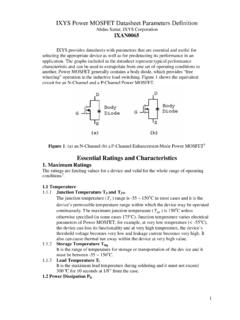
2 The data sheet should be read carefully, because PSR can be expressed either as an RTO or RTI value. PSR can be expressed as a positive or negative value in dB, depending on whether the PSRR is defined as the Power Supply change divided by the output voltage change, or vice-versa. There is no accepted standard for this in the industry, and both conventions are in use. If the amplifier has dual supplies, it is customary to express PSR separately for each. This is very useful for amplifiers that can be used in either dual or single- Supply applications. It is extremely important to remember that PSR is very much a function of ripple or noise frequency as shown in the plot for the OP1177 op amp. In most cases, the corner frequency of the roll-off follows that of the open-loop gain, and the slope is approximately 6 dB per octave (20 dB per decade).
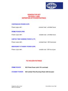
3 Typical PSR for the OP1177 is shown in Figure 1 below. SSSS Figure 1: OP1177 Power Supply Rejection (PSR) , 10/08, WK Page 1 of 3 MT-043A test setup used to measure PSRR is shown in Figure 2 below. Note that it is similar to the test setup used to measure CMRR (see Tutorial MT-042). DUT VOUT+-+-A120k 100 100 20k 10k 10k 0V+14V 15V 14V+15VS1S2 PSRR (RTI) = 1011V VOUTA1: HIGH GAIN,LOW VOS, LOW IB Figure 2: Test Setup for Measuring Power Supply Rejection Ratio (PSRR) The voltages are chosen for a symmetrical Power Supply change of 1 V. Other values may be used where appropriate, and the measurement can be made for the positive and negative Supply separately. Power SUPPLIES AND Power DISSIPATION Op amps have no ground terminal. Specifications for the Power Supply are quite often in the form X volts, but in fact it might equally be expressed as 2X volts.
4 What is important is where the CM and output ranges lie relative to the supplies. This information may be provided in tabular form or as a graph. Often data sheets will advise that an op amp will work over a range of supplies (from +3 V to V for example), and will then give parameters at several values of Supply , so that users may extrapolate. If the minimum Supply voltage is quite high, it is usually because the device uses a structure requiring a threshold voltage to function ( , zener diode). Data sheets also give current consumption. Any current flowing into one Supply pin will flow out of the other or out of the output terminal. When the output is open circuit, the dissipation is easily calculated from the Supply voltage and current. When current flows into a load, it is easiest to calculate the total dissipation (remember that if the load is grounded to the center rail the load current flows from a Supply to ground, not between supplies), and then subtract the load dissipation to obtain the device dissipation.
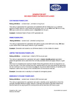
5 Data sheets normally give details of thermal resistances and maximum junction temperature ratings, from which dissipation limits may be Page 2 of 3 MT-043calculated knowing conditions. Details of further considerations relating to Power dissipation, heatsinking, etc., can be found in Chapter 7 of Reference 1. Power SUPPLIES AND DECOUPLING Because op amp PSRR is frequency dependent, op amp Power supplies must be well decoupled. At low frequencies, several devices may share a 10-50 F capacitor on each Supply , provided it is no more than 10 cm (PC track distance) from any of them. + C1C2++C3C4+VS VS LARGE AREAGROUND PLANELEAD LENGTHMINIMUMC1, C2:LOCALIZED HFDECOUPLING,LOW INDUCTANCECERAMIC, FC3, C4:SHARED LFDECOUPLING,ELECTROLYTIC,10 TO 50 F< 10cm< 10cm== Figure 3: Proper Low and High-Frequency Decoupling Techniques for Op Amps At high frequencies, each IC should have the Supply leads decoupled by a low inductance F (or so) capacitor with short leads/PC tracks.
6 These capacitors must also provide a return path for HF currents in the op amp load. Typical decoupling circuits are shown in Figure 3 above. Further bypassing and decoupling information can be found in the last chapter of References 1 and 2. REFERENCES: 1. Hank Zumbahlen, Basic Linear Design, Analog Devices, 2006, ISBN: 0-915550-28-1. Also available as Linear Circuit Design Handbook, Elsevier-Newnes, 2008, ISBN-10: 0750687037, ISBN-13: 978-0750687034. Chapter 1 2. Walter G. Jung, Op Amp Applications, Analog Devices, 2002, ISBN 0-916550-26-5, Also available as Op Amp Applications Handbook, Elsevier/Newnes, 2005, ISBN 0-7506-7844-5. Chapter 1. Copyright 2009, Analog Devices, Inc. All rights reserved. Analog Devices assumes no responsibility for customer product design or the use or application of customers products or for any infringements of patents or rights of others which may result from Analog Devices assistance.
7 All trademarks and logos are property of their respective holders. Information furnished by Analog Devices applications and development tools engineers is believed to be accurate and reliable, however no responsibility is assumed by Analog Devices regarding technical accuracy and topicality of the content provided in Analog Devices Tutorials. Page 3 of 3