Transcription of MT2000 Guided Wave Radar Level and Interface …
1 MT2000I-0202-1 Rev NC (10-2004) SPECIFICATIONS Housing Dual Compartment Powder Coated Aluminum or Stainless Steel Power 36 VDC, 2 Wire Loop Power Output 4-20 mA, HART (Secondary Output Available Via HART, RI100, or SPA HART)* LCD Display Field Selectable Units in Feet, Inches, Millimeters, Centimeters, Meters or Percentage Accuracy +/- in / 5 mm Upper Level ; +/- in / 25 mm Interface Level Resolution +/- in / mm Range 1 to 65 ft. / to meters Process Connection 3/4 NPT Standard Sensor Material 316L SS Standard, Other Materials Optional Process Pressure Up to 5000 psi (344 bar) Process Temperature Up to 800 F (427 C) Process Dielectric Constant Upper Fluid - 5, Lower Fluid 15 - 100+ Process Max Viscosity 1500 cp Approvals Factory Mutual Research Corporation XP / I / 1 / ABCD / T6 Ta = 77C DIP / II, III / 1 / EFG / T6 Ta = 77C IS / I / 1 / CD / T4 Ta = 77C - ELE1014 NI / I / 2 / ABCD / T4 Ta = 77C Type 4X CSA Canadian Standards Association XP CL I Div 1 GP ABCD CL II GP G & Coal Dust (Exia) Associated Equip.
2 , Provides Output to Sensor IS CL I Div 1 GP CD T4 CL I Div 2 GP ABCD CL II Div 2 GP G & Coal Dust when installed per ELE1014 ATEX Flameproof: II 1/2 GD EExd IIC T6 (80 C) Tamb +66 C; 02 ATEX 131713 Intrinsically Safe: II 1 GD EEx ia IIB T6 (80 C) Tamb +66 C; 02 ATEX 131712 Chinese National Supervision and Inspection Centre XP EX d IIC T6; GB , IS EX ia IIB T4; GB , MT2000 Guided Wave Radar Level and Interface Transmitter 0036 PED 0539 FEATURES Standard Single Probe Configurations Eliminate Fowling and Bridging Level and Interface Measurement with one Transmitter Weak Interface Signal Detector (Patent Pending) Widest Selection of Wetted Materials Radar Signal Travels Along the Waveguide Eliminates False Echoes and Minimizes Signal Loss No Moving Parts 2 Wire Loop Powered Linearization Table Lengths From 1 to 65 ft. / to meters Local Indication with Scrolling LCD Display Rigid, Flexible Cable & Coaxial Probes OPTIONS HART Protocol Glass Viewing Window 316L Stainless Steel Enclosure ACCESSORIES RI100 Repeater Indicator for Secondary Analog Output External Chamber Stilling Well * Note - Secondary Analog Signal Explosion Proof Areas: the RI100 - Repeat Indicator must be used Intrinsically Safe Areas.
3 The Moore Industries SPA HART must be used 2 MT2000I-0202-1 Rev NC (10-2004) MT2000 a/b/c/d/e/f/g/h/i/j/k /a Select the Probe Material S6 316L Stainless Steel Standard HC Hastelloy C-276 (Rigid Probes Only) HB Hastelloy B3 (Rigid Probes Only) MO Monel TI Titanium (Rigid Probes Only) /b Select the Transmitter Configuration L Local Transmitter Standard LW Local Transmitter with Window Cover Standard /c Select the Transmitter Housing A Dual Compartment Aluminum Housing Standard S Dual Compartment 316L Stainless Steel Housing /d Select the Process Connection / Waveguide Coupler Cxo xx Process Connection & Waveguide Coupler (Table 1) o Seal Code (no code required for /C8) (Table 2) /e Select the Probe Type Pxx Probe Code (Table 3) /f Select the Probe Attachment CDyyz-w Clamp On Centering Disk (Solid Rod Probes)* Note: Rigid probes installed in stilling wells or external chambers require centering disk.
4 CWyyz-ww Clamp On Centering Weight (Cable Probes)* Note: Cable probes require a centering weight or end fitting to stabilize bottom of cable. * A Centering Disk and Weights Guide can be found under the Data Sheet Link in the MT2000 Interace (MT2000I) Product Page in the K-TEK Website ( ) /g Select the Process Temperature Options H0 -40 to 250 F / -40 to 121 C Maximum H6 Above 250 F / 121 C; Electronics enclosure is extended 6 above process connection a (Refer to Probe Selection Chart for maximum process temperatures /h Select the Electronic Module with 4-20 mAdc Output M4A-I LCD Indicator, HART /i Select the Approvals FM Factory Mutual Research Corp. (FM) and Canadian Standards Association (CSA) CEI ATEX CEX ATEX Flameproof /j Select the Process Connection P Standard as shown on Probe Process Connection Table FL Loose flange or plug for use with probe NPT threads Specify type, material & rating from Flange Designation Chart (FLNG-0202-1)** WP Welded process connection Specify type, material and rating from Flange Designation Chart (FLNG-0202-1)* * * *The Flange Designation Guide can be found under the Data Sheet Link in the MT2000 Interface (MT2000I) Product Page in the K-TEK Website ( ) /k Select the Length L Insertion length from face of coupler in inches or millimeters ORDERING INFORMATION DESCRIPTION 0539 HOUSINGCONFIGURATIONMATERIAL TYPECABLEPROBE ATTACHMENTPROCESS CONNECTIONCOUPLERH6 INSERTION LENGTHTEMPERATURE OPTIONELECTRONICSRIGIDWINDOW/a/b/c/d/j/e /f/h/g/kPROBE3 MT2000I-0202-1 Rev NC (10-2004))
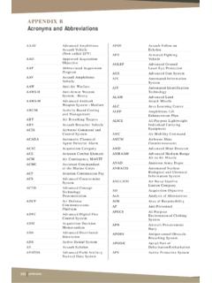
5 IL L2 L1 REQUIRED COUPLER / PROBE CONFIGURATIONS COAX (CLEAN FLUIDS ONLY) SINGLE PROBE IN STILLING WELL DUAL PROBE COUPLER PROBES /C1 /P01, /P11 /C2 /P02, /P12 INSERTION LENGTH (IL) /P01 1 < IL < 10 FT. /P02 1 < IL < 20 FT. /P11, /P12 1 < IL < 30 FT. MAX. TEMPERATURE /C1, /C2 400 F MAX. PRESSURE @ 100 F /C1, /C2 1500 PSI OPTION TO 3000 PSI UNMEASURABLE ZONES L1 4 IN. L2 1 IN. (+ weight height for P11 and P12) SINGLE PROBE IN EC CHAMBER COUPLER PROBES /C1 /P51 /C8 /P71 INSERTION LENGTH (IL) /P51, /P71 1 < IL < 22 FT. MAX. TEMPERATURE /C1 400 F /C8 800 F MAX. PRESSURE @ 100 F /C1 1500 PSI OPTION TO 3000 PSI /C8 5000 PSI UNMEASUREABLE ZONES L1 4 IN.* L2 1 IN. COUPLER PROBES /C4 /P31 /C5 /P22, /P32 INSERTION LENGTH (IL) /P22 1 < IL < 30 FT. /P31, /P32 1 < IL < 65 FT. MAX. TEMPERATURE /C4, /C5 400 F MAX. PRESSURE @ 100 F /C4, /C5 1500 PSI OPTION TO 3000 PSI UNMEASURABLE ZONES L1 4 IN. L2 2 IN. (+ Weight, Height for P31 and P32) IL L1 IL L1 L2 IL L1 L2 ML COUPLER PROBES /C1 /P01, /P11 /C2 /P02, /P12 INSERTION LENGTH (IL) /P01 1 < IL < 10 FT.
6 /P02 1 < IL < 20 FT. /P11, /P12 1 < IL < 30 FT. MAX. TEMPERATURE /C1, /C2 400 F MAX. PRESSURE @ 100 F /C1, /C2 1500 PSI OPTION TO 3000 PSI UNMEASURABLE ZONES L1 4 IN. L2 1 IN. (+ weight height for P11 and P12) L2 Note: Stilling Well Size 2 - 4 Pipe; Customer or K-TEK Supplied. 7/8 * 0 Available Upon Request. Preferred Configuration Note: Chamber Size 2 - 4 Pipe; Customer or K-TEK Supplied. Reference EC Data Sheet (EC100-0202-1) to specify / order external chamber available online at on the Displacer Replacer and External Chamber page. Preferred Configuration Flooded or Non-Flooded 4 MT2000I-0202-1 Rev NC (10-2004) TABLE 1 - PROCESS CONNECTION / WAVEGUIDE COUPLER Code Process Connection Probe Options Insulator Seal Options Temperature Rating Pressure Rating Single Probe Teflon Table 2 -60 F - 400 F -50 C - 204 C 1500 psi @ 100 F / 103 bar @ 38 C 600 psi @ 400 F / 41 bar @ 204 C /C1 3/4 NPT /P01, /P11, /P51, /PXX /C2 NPT /P02, /P12, /PXX Dual Probe With H Suffix on Coupler Code /C4 NPT /P31, /PXX 3000 psi @ 100 F / 207 bar @ 38 C 1200 psi @ 400 F / 83 bar @ 204 C /C5 2 NPT /P22, /P32, /PXX High Temp / High Pressure Borosilicate Glass N/A -60 F - 800 F -50 C - 427 C /C8 NPT /P71.
7 /PXX 5000 psi @ 100 F / 344 bar @ 38 C 1500 psi @ 800 F / 103 bar @ 427 C Suffix Description Temperature Range V Viton -40 F - 400 F / -40 C - 204 C K Kalrez -40 F - 400 F / -40 C - 204 C E EPDM -60 F - 250 F / -50 C - 125 C TABLE 2 O-RING SEALS TABLE 3 - PROBE TYPES Probe Code Description Single /P01 Rigid /P02 Rigid /P11 Cable /P12 Cable Dual /P22 Rigid /P31 Cable /P32 Cable Coaxial /P51 Rigid /P71 Rigid Custom /PXX Consult Factory MT2000 Interface GUIDELINES In order to properly detect the Level of Interface between two liquids using the MT2000 , the following rules must be adhered to: 1. One of the following probe and mounting configurations must be used: a. Single rigid rod or flexible cable mounted in a stilling well, external chamber, or existing displacer.* b. Dual rigid rod or flexible cable c. Coaxial probe mounted into tank, external chamber, or displacer * This is the preferred mounting configuration to reduce the chance of fouling.
8 2. Emulsion layers will affect the detection of an Interface Level . An emulsion layer may negate an Interface Level indication completely. The MT2000 will read an Interface Level in the presence of a 2 inch emulsion. The MT2000 is equipped with a weak Interface signal detector. This visual indication will let the user know when an emulsion layer may be present. 3. The minimum upper fluid thickness must be 4 inches when emulsion is present, and 0 inches with a clean inter face. 4. The upper fluid dielectric constant must be greater than 1. 6 and less than 5. 5. The Interface Level indication is a calculated value based par-tially upon the dielectric of the upper fluid. The upper fluid dielectric must remain constant for consistency / accuracy in the Interface Level indication. 6. The lower fluid dielectric constant must not be less than 15. 7. If the application is a flooded condition (sensor completely submerged in process), it must remain completely flooded.
9 8. In a non-flooded condition, the upper fluid must not be allowed to enter the upper unmeasurable zone. The upper unmeasur-able zone is typically located within the mounting nozzle of the vessel. If the required Interface application does not fall within the above mentioned parameters, please consult the factory for an alternate technology, such as a Magnetostrictive, Magnetic Level Gauge or RF Capacitance.