Transcription of Multi-Layer Ceramic Capacitors: Why and How They Fail
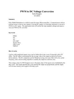
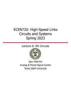
1 Multi-Layer Ceramic capacitors : Why and How They Fail Property of Passive Plus, Inc. 1 PPI MLCC materials and processes Lifetime limitations of materials Manufacturing shortcomings and defects When Bad Things Happen to Good Customers: Mishandling and design inadequacies Reliability models and testing PPI 2 Property of Passive Plus, Inc. Multi-Layer Ceramic Capacitor (MLCC) PPI 3 Property of Passive Plus, Inc. MLCC Mounted on Microstrip PPI 4 Fig. 2. Vertically mounted multilayer chip capacitor on microstrip (top view "through" dielectric cover layer)microstrip substratetracecapacitorSection R-RRRterminationFeatures: (1) A Ceramic brick with interleaved metallic electrodes (2) Soldered across a gap in microstrip center conductor (shown) or extending from center conductor to ground plane (not shown) (2) Shown oriented with electrodes vertical to substrate Property of Passive Plus, Inc.
2 Design Includes Tradeoffs Among Many Factors Selection of materials In manufacture of MLCC: dielectrics, electrode metal inks, termination metallization In subsequent use and handling by customer: RoHS compliance, solderability, re-usability, marking requirements Electrical Requirements Meeting all specifications on capacitance, tolerance, working voltage , temperature variation, loss at operating frequency, magnetic properties, reliability, etc. Mechanical Requirements Physical size, lead pull strength, bending moment, permeability to solvents, etc. PPI 5 Property of Passive Plus, Inc. MLCC Fabrication Processes and Materials Tape-based process Magnesium titanate dielectric, typical temp.
3 Characteristic is P90 (cap change 90 20 ppm/ 0C), PPI P series, but can be doped with rare earths to produce NPO (=COG) temperature characteristic (cap change 30 ppm/ 0C), PPI C series Barium titanate dielectric, PPI N series; can be doped to produce X7R characteristic: 15% cap change, max. from -54 to +100 0C, , PPI X series (X7R) Wet process Can achieve much higher capacitance values than tape-based processes (thinner dielectric layers), but Typically more loss at RF frequencies than tape-based capacitors Can be doped to produce NPO, X7R, Y5Z, etcetera temperature characteristics PPI Property of Passive Plus, Inc.
4 6 High-Fire and Low-fire Ceramics High-Fire Sinters at 1350 0C Palladium or platinum electrodes Pd bulk resistivity = 11 x 10-6 ohm-cm. Example: PPI C and P series Low-fire Sinters at 950-1050 0C Silver or silver/palladium electrodes Ag bulk resistivity = x 10-6 ohm-cm. Example: PPI N series Property of Passive Plus, Inc. 7 PPI Cost Drivers - High-fire/Low-fire High-fire Palladium electrodes High pressure - small block size Dual firing / diamond sawing Low-fire Silver or Silver-Palladium electrodes Lower pressure larger block size Single Co-firing of Ceramic + electrodes Dice green Property of Passive Plus, Inc.
5 8 PPI Manufacturing Steps: Tape-based Process Inspect and process incoming Ceramic powder Mix powder in viscous liquid (organic binder + plasticizer in solvent) to form slurry, and cast tape using doctor blade Print electrode pattern on tape using palladium or silver inks Spank printed squares of Ceramic tape, alternate layer orientations, stack printed squares, press together Dry stacks in oven, dice (singulate) bisque Sinter in ovens (at 950 -1350 0C) Corner round Use Chipstar machine to apply silver or nickel terminations Apply nickel barrier (if silver termination) Apply solder plate or tin plate PPI 9 Property of Passive Plus, Inc.
6 Electrode Patterns Full overlap Floater Split PPI 10 Property of Passive Plus, Inc. More Electrode Patterns 60% overlap Multi-column Doubled electrodes PPI 11 Property of Passive Plus, Inc. MLCC Specifications and Notes (1): Tolerance Bins Specification Cap value Tolerance Physical dimensions WVDC, DWV, WVAC DF and ESR FSR and FPR TCC & VCC Current/Power handling Magnetic/Non-magnetic Termination metallization Tolerance bins: If you order a 5% capacitor, you likely will receive values from (+3% - pF) to (+5% - pF) and -3% + pF to (-5% + pF) Measurement uncertainty guard band PPI Property of Passive Plus, Inc.
7 Nominal Value -5% -2% , Guard Band +5% +2% MLCC Specifications and Notes (2): EIA Sizes Specification Cap value Tolerance Physical dimensions WVDC, DWV, WVAC DF and ESR FSR and FPR TCC & VCC Current/Power handling Magnetic/Non-magnetic Termination metallization EIA sizes are industry standards for physical dimensions and tolerances Advantages: Provide users with a wide range of vendor choices.
8 (Mainly for non-RF capacitors ; RF capacitors can have the same physical size and capacitance, but still differ in high-frequency performance.) Permit standardization of mounting pad layout Permit optical orientation of capacitors Resist tombstoning during soldering Disadvantages: Do not necessarily provide the best tradeoffs among parameters determining electrical performance (near-square shapes are often better) PPI Property of Passive Plus, Inc. 13 MLCC Specifications and Notes (3): AC voltage & FSR Specification Cap value Tolerance Physical dimensions WVDC, DWV, WVAC DF and ESR FSR and FPR TCC & VCC Current/Power handling Magnetic/Non-magnetic Termination metallization WVAC may be significantly lower than WVDC.
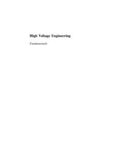
9 Breakdown may be external or internal FSR in the series mode depends on substrate thickness & dielectric constant, capacitor orientation, and mounting pad dimensions PPI Property of Passive Plus, Inc. 14 MLCC Specifications and Notes (4): RoHS and Termination Metallization Specification Cap value Tolerance Physical dimensions WVDC, DWV, WVAC DF and ESR FSR and FPR TCC and VCC Current/Power handling Magnetic/Non-magnetic Termination metallization PPI Property of Passive Plus, Inc. 15 Dielectric ( RD) and Metallic ( RM) Losses Property of Passive Plus, Inc. 16 fCRD 2tan where = dielectric loss tangent tanf = frequency at which RD is measured Rm C = capacitance value PPI number of electrodes, resistivity, electrode aspect ratio, skin effect in thickness dimension (even and odd modes within electrodes), and skin effect (frequency-dependent edge effect) in width dimension Typical Equivalent Series Resistance (ESR) as a Function of Frequency PPI Property of Passive Plus, Inc.
10 17 (MilliOhms) Frequency (MHz) Total ESR Total ESRM etallic Loss dominant Dielectric Loss dominant MLCC Failure Classifications Intrinsic Electronic disorder, lattice defects, and grain boundaries Extrinsic Voids, cracks, and de-laminations; electrode porosity; termination lift Customer Induced Electrical (current or voltage ) overstress Thermal stress from soldering operations Mechanical stress (PCB flexure, pick-and-place operations) PPI 18 Property of Passive Plus, Inc. Intrinsic Failure in Dielectric-Metal Systems If a DC voltage is placed on a parallel-plate capacitor, a leakage current results; the ratio of the voltage to this leakage current is called the insulation resistance (IR), and is used as one measure of a capacitor s integrity.