Transcription of MULTILAYER CERAMIC CAPACITORS Low Profile …
1 MULTILAYER CERAMIC CAPACITORS Approval Sheet Page 1 of 9 ASC_ Low Profile_(TT)_009Q_AS Sep. 2017 *Contents in this sheet are subject to change without prior notice. MULTILAYER CERAMIC CAPACITORS Low Profile Series 0402 to 1210 Sizes X7R, X5R & Y5V Dielectrics Halogen Free & RoHS Compliance MULTILAYER CERAMIC CAPACITORS Approval Sheet Page 2 of 9 ASC_ Low Profile_(TT)_009Q_AS Sep.
2 2017 1. DESCRIPTION MLCC consists of a conducting material and electrodes. To manufacture a chip-type SMT and achieve miniaturization, high density and high efficiency, CERAMIC condensers are used. WTC TT series MLCC is used in product having thickness concerned generally have high capacitance and thinner product thickness. The high dielectric constant material X7R, X5R and Y5V are used for this series product. 4. HOW TO ORDER TT 15 X 475 M 6R3 C T Series TT=Low Profile Size 15=0402 (1005) 18=0603 (1608) 21=0805 (2012) 31=1206 (3216) 32=1210 (3225) Dielectric B=X7R X=X5R F=Y5V Capacitance Two significant digits followed by no.
3 Of zeros. And R is in place of decimal point. eg.: 475=47x105 =4,700,000pF = F Tolerance K= 10% M= 20% Z=-20/+80% Rated voltage Two significant digits followed by no. of zeros. And R is in place of decimal point. 6R3= VDC 100=10 VDC 160=16 VDC 250=25 VDC 500=50 VDC 101=100 VDC Termination C=Cu/Ni/Sn Packaging T=7 reeled G=13 reeled 2. FEATURES a. Standard size with thin thickness. b. Small size with high capacitance. c. Capacitor with lead-free termination (pure Tin).
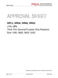
4 3. APPLICATIONS a. For LCD panels. b. For PCMCA cards. c. For IC packaging and modules. d. Any thickness concerned products. MULTILAYER CERAMIC CAPACITORS Approval Sheet Page 3 of 9 ASC_ Low Profile_(TT)_009Q_AS Sep. 2017 5. EXTERNAL DIMENSIONS 6. GENERAL ELECTRICAL DATA Dielectric X7R X5R Y5V Size 0402, 0603, 0805, 1206, 1210 Capacitance range* 1 F to 10 F F to 22 F 1 F to 10 F Capacitance tolerance** K ( 10%), M ( 20%) Z (-20/+80%) Rated voltage (WVDC) 10V, 16V, 25V, 50V, 100V , 10V, 16V, 25V 10V, 16V, 25V, 50V Operating temperature -55 to +125 C -55 to +85 C -25 to +85 C Capacitance characteristic 15% +30/-80% Termination Ni/Sn (lead-free termination)
5 * Measured at , 10%, 30~70% related humidity, 25 C ambient temperature for X7R, X5R and at 20 C for Y5V. ** Preconditioning for Class II MLCC: Perform a heat treatment at 150 10 C for 1 hour, then leave in ambient condition for 24 2 hours before measurement. TWLMBMB Fig. 1 The outline of MLCC Size Inch (mm) L (mm) W (mm) T (mm)/Symbol MB (mm) 0402 (1005) L 0603 (1608) + + H 0805 (2012) T 1206 (3216) T J 1210 (3225) T K * Reflow soldering process only is recommended.
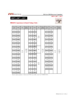
6 MULTILAYER CERAMIC CAPACITORS Approval Sheet Page 4 of 9 ASC_ Low Profile_(TT)_009Q_AS Sep. 2017 7. CAPACITANCE RANGE 7-1 X7R dielectric Dielectric X7R Size 0805 1206 1210 Rated voltage (VDC) 10 16 25 50 10 16 25 50 10 16 100 Capacitance F (105) T F (155) F (225) T T T K F (335) F (475) T T F (685) 10 F (106) T 22 F (226) 7-2 X5R dielectric Dielectric X5R Size 0402 0603 0805 1206 1210 Rated voltage (VDC) 10 25 10 16 10 16 25 10 16 25 50 10 16 25 Capacitance (224)
7 L H H (474) L L F (105) L H H T T T T T T F (155) T T T T T F (225) L T T T T T T T T F (335) T T T T F (475) L H T T T T T T T T F (685) 10 F (106) T T T J J/T T T T 22uF (226) T T T T T 47uF (476) T 7-3 Y5V dielectric Dielectric Y5V Size 0805 1206 1210 Rated voltage (VDC) 10 16 25 50 10 16 25 50 10 16 Capacitance F (105) T F (155) F (225) T T T T T F (335) T F (475) T T T T F (685) T 10 F (106) T T T 22 F (226) 8.
8 PACKAGING STYLE AND QUANTITY Size Thickness Max (mm)/Symbol 7 reel Paper tape Plastic tape 0402 (1005) L 15k - 0603 (1608) H 4k - 0805 (2012) T 4k - 1206 (3216) T 4k - J - 3k 1210 (3225) T - 3k K - 1k Unit: pieces MULTILAYER CERAMIC CAPACITORS Approval Sheet Page 5 of 9 ASC_ Low Profile_(TT)_009Q_AS Sep.
9 2017 9. RELIABILITY TEST CONDITIONS AND REQUIREMENTS No. Item Test Condition Requirements 1. Visual and Mechanical --- * No remarkable defect. * Dimensions to conform to individual specification sheet. 2. Capacitance Cap 10 F, , 1kHz 10% Cap>10 F, , 120Hz 20%** ** Test condition: 1 KHz 10% TT18X 475(10V) , TT15X series *Before initial measurement (Class II only): To apply de-aging at 150 C for 1hr then set for 24 2 hrs at room temp. * Shall not exceed the limits given in the detailed spec.
10 3. Q/ (Dissipation Factor) X7R/X5R: Rated vol. 100V 5% 50V, 25V, 16V, 10V 10% 15% Y5V: Rated vol. 50V 7% 25V 9% 16V/10V 4. Dielectric Strength * To apply voltage: 250% rated voltage. * Duration: 1 to 5 sec. * Charge and discharge current less than 50mA. * No evidence of damage or flash over during test. 5. Insulation Resistance * To apply rated voltage for max. 120 sec. * Before initial measurement (Class II only): To apply de-aging at 150 C for 1hr then set for 24 2 hrs at room temp.