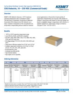
Transcription of MULTILAYER CERAMIC CHIP CAPACITORS - GMC SERIES
1 MULTILAYER CERAMIC Chip CAPACITORS - GMC SERIES constructionSolder plate; 100% matte SN; typical thickness to *(please see note) PZ---Nickel Barrier Layer (50 Micro-inches Electroplated Nickel min.) ., Introduction ?""'I.,__ Inner Electrodes - Constructed by screen printing alternativelayers of internal metallic electrodes ontoceramic dielectric materials and firinginto a concrete monolithic body, then completedby application of metal end terminations whichare fired to assure permanent bonding with theindividual internal electrodes , Chip Capacitor Selection DIELECTRIC TYPE Applications-Can be used on surface mount assembly equipment- Our fully integrated manufacturing and total qualitycontrol systems ensure unprecedented high standards ofquality and reliability.
2 Features-Large capacitance values in small sizes-Excellent high frequency characteristicsCOG (NPO) Capacitance change with temperature is 0-30ppml C which is less than C from -55 C to +125 C. Typical capacitance change with life is less % for NPOs, one-fifth that shown by most other dielectrics. NPO formulationsshow no aging stable class I dielectric: linear temperature coefficient, low loss, negligible change of electrical properties with time, voltage and frequency. Operating Temperature Temperature Coefficient Range -55 C0 30ppm Cto+125 CCalchip Electronics, INC. Phone: (215) 942-8900 Temperature Voltage Dissipation Coefficient Factor ( cMax@ Vocw) 0 30ppm/ Max, Typical Insulation Dielectric Resistance withstanding Voltage 25 C, VDCW::3 XVocw >100 GOF or1000QF,whichever is less 125 C, Vocw:>10 GQF or100 QFwhichever is lessTest Aging Rate Parameters 0% per C$1000pFdecade hour f=1 MHzV= C C>1000pFf=1 KHzV= Fax : (215) 942-6400 X7R/X5R Its temperature variation of capacitance is within 15% from -55 C to +125 C (-55 C to +85 C for XSR).
3 The capacitance change is class 11 dielectric Temperature Operating Temperature Voltage Dissipation Insulation Dielectric Test Temperature Coefficient Coefficient Factor Resistance withstanding Aging Rate Parameters Range X7R= -55C to +125C X5R= -55C to +85 Czsu YSV { cMax@ Voltage Vocw) 15% X7R/X5R Max, 25 C, VDCW:: Vocw <2% per 1 KHz, Not Applicable Typical >100 GQFor decade hour 1000QF, whichever is less25 C 125 C, Vocw:values> or >10 GQF or= to 10uF 100QF whichever is less 120Hz Despite their capacitance instability, ZSU formulations are very popular because of their small size, temperature range low ESL, low ESR and excellent frequency response. These features are particularly important for decoupling application where only a minimum capacitance value is required.}
4 YSV formulations are for general purpose use in a limited temperature range. They have a wide temperature characteristic of +22% - 82% capacitance change over the operating temperature range of -30 C to +85 C. YSVs high dielectric constant allows the manufacture of very high capacitance values (up to 22MF) in small physical sizes. High capacitance per unit volume: general purpose product Operating Temperature Dissipation Insulation Dielectric Test Temperature withstanding Aging Rate Range Coefficient Factor Resistance Voltage Parameters -30 C +22% Max, 10GQ or 100QF XVocw per 1 KHz, 1 Vrms 25 C to -82% Typical whichever is decade hour values> or +85 Cless, = to 10uF 25 C, Vocw 120Hz CAPACITANCE VALUE & TOLERANCE Determined by circuit requirements.
5 Note that chip prices decrease with lower capacitance value and looser tolerance. VOLTAGE Determined by circuit requirements. Units are designed to exceed the withstanding voltage specification, , the user need not incorporate an additional safety margin. Calchip Electronics, INC. Phone: (215) 942-8900 Fax : (215) 942-6400 CAPACITOR SIZE Select the smallest unit permitted by the circuit constraints that provides the required capacitance and voltage rating. All Cal-Chip CAPACITORS conform to EIA specifications. CAPACITOR TERMINATION Nickel barrier is standard and recommended for units exposed to repeated solder cycles, to minimize leaching of the termination.. Note: Cal-Chip has completed the Lead-Free transition.
6 All parts shipped will be lead-free. The customer designator of "LF" is no longer available. Lead-Free material will continue to have a green RoHS symbol on the label. Calchip Electronics, INC. Phone: (215) 942-8900 Fax : (215) 942-6400 GMC21CG102J50 NTDP roduct DimensionsDielectricCapacitanceTolerance VoltageTerminationPackagingTypeDC01: 01005CG: COG/NPO0R5: : : Sn/Ni02: 02015R0: : : Pd/Ag04: 0402100: 10pF10: 10V10: 0603101: 100pF16: 16V21: 0805X7RX5RZ5UY5V102: 1000pF25: 25V31: 1206103: .01uF35: 35V32: 1210104: .1uF50: 50V40: 1808105: : 63V43: 1812106: 10uFB: + : + : + : +/-1%G: +/-2%J: +/-5%K: +/-10%M: +/-20%Z: -20%/+80% 100: 100V45: 1825107: 100uF200: 200V55: 222057: 2225 Blank: 7" reelD: See BelowG: See BelowQ: See BelowPACKAGING 10"/13" REELS ONLYTypeDGQ020150K040250K060310K15K08051 0K15K20K120610K15K20K12104K8K10K18088K18 122K8K182522202225 Code01005 DIMENSION (MM) GMC01 L(Ll) w H BW(L2/L3) - dielectric NPO/COG X7R XSR YSV/ZSU Rated Voltage 10/16 10 10 16 0 '-n.
7 , .. 1 1Rn 1R2 1 c; 1R5 2R7 "'! "'! "'!R"'l 3R9 4 7 4R7 <; F, c:oi:: 6R8 R 'J RQ'J 10 inn 11 110 17 15 1,;n 18 180 20 7nn7? 710 27 270 30 :tnn "'!"'! -:no39 390 43 11::tn 47 470 51 510 <;F, c:i::n 62 i-?n68 680 82 sno 1nn 101 120 121 150 1 <;1 Hln 181 220 221 270 771 -:t-:tn '.l.'. 390 391 ,110 4/1 560 c;i:;1 680 681 R?O R?1 1 On 1n? 122 1<;? 1 R 1 R'J 222 27 772 -:t-:t -:t-:t? 392 47 471 t;l,'J 682 R?? 10 1n:t 12 123 15 1 <;:t 1R 1R"l 22 223 27 273 -:t:t -:t-:t-:t 39 393 47 4/ 56 t;l,";t 68 683 82 R?-:t 1M 120 124 0201Y5V/Z5U25504 (MM)GMC02L(L1) VoltageCap. (L2/L3) (MM)L(L1) VoltageCap. RangeHBW(L2/LW) ~ & Z5U0402 0402 **Please note L/W/H deviation for the 22uF is + ** 162550 100 200 16/25 50 100 200 ~ & Z5 URated VoltageCap.
8 RangeHBW(L2/LW)dielectricDIMENSION (MM)L(L1) Calchip Electronics, INC. Phone: (215) 942-8900 Fax : (215) 942-6400 2550 100 16 16 25 50 100 16 25 maxDIMENSION (MM)GMC10L(L1) & Z5 URated VoltageCap. RangeBW(L2/LW) ~ & Z5 URated VoltageCap. RangeBW(L2/LW) ~ maxDIMENSION (MM)GMC10L(L1) through 1210 (COG/NPO)0805 through 1210 (COG/NPO) (cont)1808 -2225 (COG/NPO) Cal-Chi Electronics Inc . DIMENSION (MM) GMC40 GMC43 GMC45 GMCSS GMC57 L(Ll) w H BW(L2/L3) Rated Voltage 50 100 200 50 100 200 50 100 200 50 100 200 50 100 200 lOnf 100 11 110 12 120 13 130 15 150 16 160 18 180 20 200 22 220 24 240 27 270 30 300 33 330 36 360 39 390 43 430 47 470 51of 510 56 560 62 620 68 680 75 750 82 820 91 910 100 101 120 121 130 131 150 151 160 161 180 181 200 201 220 221 240 241 270 271 300 301 330 331 360 361 390 391 430 431 470 471 510 511 560 561 680 681 750 751 820 821 910 911 102 122 152 182 222 242 272 332 392 472 562 682 822 10 103 12 123 15 153 18 183 22 223 27 273 33 333 39 393 47 473 56 563 68 683 82 823 100 104 120 124 150 154 180 184 220 224 270 274 330 334 470 474 VoltageCap.
9 ~ (L2/L3)DIMENSION (MM)L(L1) ~ ~ - 1210 (MM) (L1) ~ ~ ~ VoltageCap. RangeBW(L2/L3) ~ ~ -2225 (X7R) ( cont) 0805- 2220 (X5R) 0805- 2220 (Y5V/Z5U) GMC32X5R (1210) size ( L) t olerance for values > 100uf, t olerance increases to +/- 0. 4 ( MM)L(L1) (L2/L3)Rated VoltageCap. ~ ~ ~ ~ ~ 16 25 35 50 634 16 25 504 16 25 16 16 25 50180 GMC32X5R (1210) size (L) tolerance for values > 100uf, tolerance increases to +/- (MM)L(L1) (L2/L3)Rated VoltageCap. ~ ~ ~ ~ ~ (Taping) Standard Reel Unit:mm (Reel Type-Size) A B C D E w t R 0178 050 min.
10 + E optional 10/13 inch reels Unit:mm A B C D E w t R R 0330 050 + CarrierTape (Standard) To peel off the cover tape by the method shown in theright figure apply a peel-off force of 20 gt 60 gt (cardboard); 10 gt - 75 gt (plastic tape).Top Cover Tape 165-180 Cover Tape tension /======::;;;::::==== direction The cover tape should not touch the top or bottom of If the cover tape has been peeled off it may be difficult toremove the chip due to punch-hole clearance, dirt, anddebris. Make sure therefore that no paper waste willadhere to and block the absorpti on nozzle. If the cover tape has been peeled off from the top, stick itback on with a suitable adhesive.