Transcription of MX25L4005, MX25L8005 - mct.net
1 REV. , MAY. 31, 20051P/N: PM1130MX25L4005, MX25L80054M/8M-BIT [x 1] CMOS SERIAL FLASHPRELIMINARYFEATURESGENERAL Serial Peripheral Interface (SPI) compatible -- Mode 0and Mode 3 4,194,304 x 1 bit structure for 4M; 8,388,608 x 1 bitstructure for 8M 128 Equal Sectors with 4K byte each ( mx25l4005 )256 Equal Sectors with 4K byte each ( MX25L8005 )- Any Sector can be erased individually 8 Equal Blocks with 64K byte each ( mx25l4005 )16 Equal Blocks with 64K byte each ( MX25L8005 )- Any Block can be erased individually Single Power Supply Operation- to volt for read, erase, and program operations Latch-up protected to 100mA from -1V to Vcc +1V Low Vcc write inhibit is from to High Performance- Fast access time: 70 MHz serial clock (15pF + 1 TTLLoad) and 66 MHz serial clock (30pF + 1 TTL Load)- Fast program time: (typ.)
2 And 5ms(max.)/page(256-byte per page)- Fast erase time: 90ms(typ.) and 270ms(max.)/sector(4K-byte per sector) ; 1s(typ.) and 3s(max.)/block (64K-byte per block) Low Power Consumption- Low active read current: 12mA(max.) at 70 MHz,8mA(max.) at 66 MHz and 4mA(max.) at 33 MHz- Low active programming current: 30mA (max.)- Low active erase current: 15mA (max.)- Low standby current: 50uA (max.)- Deep power-down mode 1uA (typical) Minimum 100,000 erase/program cyclesSOFTWARE FEATURES Input Data Format- 1-byte Command code Block Lock protection- The BP0~BP2 status bit defines the size of the areato be software protected against Program and Eraseinstructions. Auto Erase and Auto Program Algorithm- Automatically erases and verifies data at selectedsector- Automatically programs and verifies data at selectedpage by an internal algorithm that automatically timesthe program pulse widths (Any page to be programedshould have page in the erased state first) Status Register Feature Electronic Identification- JEDEC 2-byte Device ID- RES command, 1-byte Device IDHARDWARE FEATURES SCLK Input- Serial clock input SI Input- Serial Data Input SO Output- Serial Data Output WP# pin- Hardware write protection HOLD# pin- pause the chip without diselecting the chip PACKAGE- 8-pin SOP (150mil)- 8-pin SOP (200mil)- 8-land SON (6x5mm)2P/N: PM1130 REV.
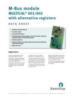
3 , MAY. 31, 2005MX25L4005, MX25L8005 PIN CONFIGURATIONSSYMBOLDESCRIPTIONCS#Chip SelectSISerial Data InputSOSerial Data OutputSCLKC lock InputHOLD#Hold, to pause the device withoutdeselecting the deviceWP#Write ProtectionVCC+ Power SupplyGNDG roundPIN DESCRIPTIONGENERAL DESCRIPTIONThe mx25l4005 is a CMOS 4,194,304 bit serial Flashmemory, which is configured as 524,288 x 8 internally. TheMX25L8005 is a CMOS 8,388,608 bit serial Flash memory,which is configured as 1,048,576 x 8 internally. TheMX25L4005 and MX25L8005 feature a serial peripheralinterface and software protocol allowing operation on asimple 3-wire bus. The three bus signals are a clock input(SCLK), a serial data input (SI), and a serial data output(SO). SPI access to the device is enabled by CS# mx25l4005 and MX25L8005 provide sequential readoperation on whole program/erase command is issued, auto program/erase algorithms which program/ erase and verify thespecified page or byte /sector/block locations will beexecuted.
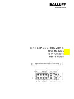
4 Program command is executed on page (256bytes) basis, and erase command is executes on chip orsector(4K-bytes) or block(64K-bytes).To provide user with ease of interface, a status register isincluded to indicate the status of the chip. The status readcommand can be issued to detect completion status of aprogram or erase operation via WIP the device is not in operation and CS# is high, it isput in standby mode and draws less than 50uA DC mx25l4005 and MX25L8005 utilize MXIC's propri-etary memory cell, which reliably stores memory contentseven after 100,000 program and erase SOP (150/200mil)8-LAND SON (6x5mm)1234CS#SOWP#GND8765 VCCHOLD#SCLKSI1234CS#SOWP#GNDVCCHOLD#SCL KSI87653P/N: PM1130 REV. , MAY. 31, 2005MX25L4005, MX25L8005 BLOCK DIAGRAMA ddressGeneratorMemory ArrayPage BufferY-DecoderX-DecoderDataRegisterSRAM B ufferSISCLKC lock GeneratorStateMachineModeLogicSenseAmpli fierHVGeneratorOutputBufferSOCS#4P/N: PM1130 REV.
5 , MAY. 31, 2005MX25L4005, MX25L8005 DATA PROTECTIONThe mx25l4005 , MX25L8005 are designed to offerprotection against accidental erasure or programmingcaused by spurious system level signals that may existduring power transition. During power up the deviceautomatically resets the state machine in the Read addition, with its control register architecture, alterationof the memory contents only occurs after successfulcompletion of specific command sequences. The devicealso incorporates several features to prevent inadvertentwrite cycles resulting from VCC power-up and power-downtransition or system noise. Power-On Reset and an internal timer (tPUW) canprovide protection against inadvertant changes whilethe power supply is outside the operating specification.
6 Program, Erase and Write Status Register instructionsare checked that they consist of a number of clockpulses that is a multiple of eight, before they areaccepted for execution. All instructions that modify data must be preceded bya Write Enable (WREN) instruction to set the WriteEnable Latch (WEL) bit . This bit is returned to its resetstate by the following events:- Power-up- Write Disable (WRDI) instruction completion- Write Status Register (WRSR) instruction completion- Page Program (PP) instruction completion- Sector Erase (SE) instruction completion- Block Erase (BE) instruction completion- Chip Erase (CE) instruction completion The Block Protect (BP2, BP1, BP0) bits allow part ofthe memory to be configured as readonly. This is theSoftware Protected Mode (SPM).
7 The Write Protect (WP#) signal allows the BlockProtect (BP2, BP1, BP0) bits and Status RegisterWrite Disable (SRWD) bit to be protected. This is theHardware Protected Mode (HPM). In addition to the low power consumption feature, theDeep Power-down mode offers extra software protec-tion from inadvertent Write, Program and Erase in-structions, as all instructions are ignored except oneparticular instruction (the Release from DeepPowerdown instruction). To avoid unexpected changes by system power supplytransition, the Power-On Reset and an internal timer(tPUW) can protect the device. Before the Program, Erase, and Write Status Registerexecution, instruction length will be checked on follow-ing the clock pulse number to be multiple of eight base.
8 Write Enable (WREN) instruction must set to WriteEnable Latch (WEL) bit before writing other instructionsto modify data. The WEL bit will return to reset state byfollowing situations:- Power-up- Write Disable (WRDI) instruction completion- Write Status Register (WRSR) instruction completion- Page Program (PP) instruction completion- Sector Erase (SE) instruction completion- Block Erase (BE) instruction completion- Chip Erase (CE) instruction completion The Software Protected Mode (SPM) use (BP2, BP1,BP0) bits to allow part of memory to be protected asread only. The Hardware Protected Mode (HPM) use WP# toprotect the (BP2, BP1, BP0) bits and SRWD bit. Deep-Power Down Mode also protects the device byignoring all instructions except Release from Deep-Power Down (RDP) instruction and RES : PM1130 REV.
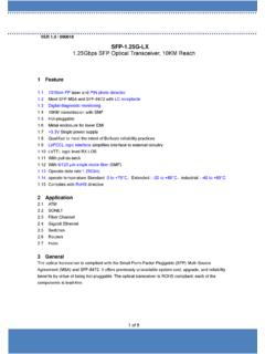
9 , MAY. 31, 2005MX25L4005, MX25L8005 Table 1. Protected Area SizesStatus bitProtect level4Mb8 MbBP2BP1BP00000 (none)NoneNone0011 (1 block)Block 7 Block 150102 (2 blocks)Block 6-7 Block 14-150113 (4 blocks)Block 4-7 Block 12-151004 (8 blocks)AllBlock 8-151015 (All)AllAll1106 (All)AllAll1117 (All)AllAll6P/N: PM1130 REV. , MAY. 31, 2005MX25L4005, MX25L8005 HOLD FEATUREHOLD# pin signal goes low to hold any serial communications with the device. The HOLD feature will not stop the operationof write status register, programming, or erasing in operation of HOLD requires Chip Select(CS#) keeping low and starts on falling edge of HOLD# pin signal while SerialClock (SCLK) signal is being low (if Serial Clock signal is not being low, HOLD operation will not start until Serial Clocksignal being low).
10 The HOLD condition ends on the rising edge of HOLD# pin signal while Serial Clock(SCLK) signal isbeing low( if Serial Clock signal is not being low, HOLD operation will not end until Serial Clock being low), see Figure 1. Hold Condition OperationThe Serial Data Output (SO) is high impedance, both Serial Data Input (SI) and Serial Clock (SCLK) are don't care duringthe HOLD operation. If Chip Select (CS#) signal goes high during HOLD operation, it has the effect on resetting the internallogic of the device. It is necessary to drive HOLD# signal to high, and then to drive CS# to low for restarting communicationwith the #SCLKHoldCondition(standard use)HoldCondition(non-standard use)7P/N: PM1130 REV. , MAY. 31, 2005MX25L4005, MX25L8005 Table 2.