Transcription of NASA Systems Engineering Handbook
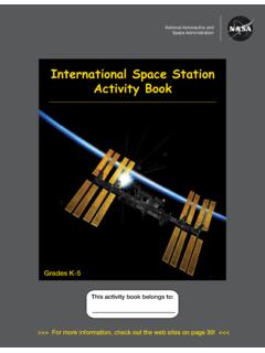
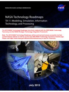
1 National Aeronautics and Space AdministrationNASA Systems Engineering SP-2016-6105 Rev2 supersedes SP-2007-6105 Rev 1 dated December, photos: Top left: In this photo, engineers led by researcher Greg Gatlin have sprayed fluorescent oil on a percent scale model of a futuristic hybrid wing body during tests in the 14- by 22-Foot Subsonic Wind Tunnel at NASA s Langley Research Center in Hampton, VA. The oil helps researchers see the flow patterns when air passes over and around the model. (NASA Langley/Preston Martin) Top right: Water impact test of a test version of the Orion spacecraft took place on August 24, 2016, at NASA Langley Research Center (NASA) Bottom left: two test mirror segments are placed onto the support structure that will hold them. (NASA/Chris Gunn) Bottom right: This self-portrait of NASA s Curiosity Mars rover shows the vehicle at the Mojave site, where its drill collected the mission s second taste of Mount Sharp.
2 (NASA/JPL-Caltech/MSSS)Comments, questions, and suggestions regarding this document can be sent to:Steven R. HirshornChief Engineer, Aeronautics Research Mission Directorate (ARMD)Office of the Chief EngineerNASA Headquarters, Room 6D37300 E St SWWashington, DC Systems Engineering HANDBOOKT able of ContentsPreface viiiAcknowledgments Introduction Purpose .. Scope and Depth .. Fundamentals of Systems Engineering The Common Technical Processes and the SE Engine .. An Overview of the SE Engine by Project Phase .. Example of Using the SE Engine .. Distinctions between Product Verification and Product Validation .. Cost Effectiveness Considerations .. Human Systems Integration (HSI) in the SE Process .. Competency Model for Systems Engineers.
3 NASA Program/Project Life Cycle Program Formulation .. Program Implementation .. Project Pre-Phase A: Concept Studies . Project Phase A: Concept and Technology Development .. Project Phase B: Preliminary Design and Technology Completion .. Project Phase C: Final Design and Fabrication .. Project Phase D: system Assembly, Integration and Test, Launch .. Project Phase E: Operations and Sustainment .. Project Phase F: Closeout .. Funding: The Budget Cycle .. Tailoring and Customization of NPR 7123 .1 Requirements .. Introduction Criteria for Tailoring Tailoring SE NPR Requirements Using the Compliance Matrix Ways to Tailor a SE Requirement Examples of Tailoring and Customization Approvals for Tailoring system Design Processes Stakeholder Expectations Definition .. Process Description Stakeholder Expectations Definition Guidance Technical Requirements Definition.
4 Process Description Technical Requirements Definition Guidance Logical Decomposition .. Process Description Logical Decomposition Guidance Design Solution Definition .. Process Description Design Solution Definition Guidance Product Realization Product Implementation .. Process Description Product Implementation Guidance Product Integration .. Process Description Product Integration Guidance Product Verification ..88ivNASA Systems Engineering HANDBOOKT able of Process Description Product Verification Guidance Product Validation .. Process Description Product Validation Guidance Product Transition .. Process Description Product Transition Guidance Crosscutting Technical Management Technical Planning .. 113 Process Description Technical Planning Guidance Requirements Management .. Process Description Requirements Management Guidance Interface Management.
5 Process Description Interface Management Guidance Technical Risk Management .. Risk Management Process Description Risk Management Process Guidance Configuration Management .. Process Description CM Guidance Technical Data Management .. Process Description Technical Data Management Guidance Technical Assessment .. Process Description Technical Assessment Guidance Decision Analysis .. Process Description Decision Analysis Guidance 170 Appendix A Acronyms .. 173 Appendix B Glossary .. 176 Appendix C How to Write a Good Requirement Checklist .. 197 Appendix D Requirements Verification Matrix .. 201 Appendix E Creating the Validation Plan with a Validation Requirements Matrix .. 203 Appendix F Functional, Timing, and State Analysis 205 Appendix G Technology Assessment/Insertion .. 206 Appendix H Integration Plan Outline.
6 214 Appendix I Verification and Validation Plan Outline 216 Appendix J SEMP Content Outline .. 223 Appendix K Technical Plans .. 235 Appendix L Interface Requirements Document Outline .. 236 Appendix M CM Plan Outline ..239 Appendix N Guidance on Technical Peer Reviews/Inspections .. 240 Appendix O Reserved .. 241 Appendix P SOW Review Checklist .. 242 Appendix Q Reserved .. 243 Appendix R HSI Plan Content Outline .. 244 Appendix S Concept of Operations Annotated Outline .. 251 Appendix T Systems Engineering in Phase E .. 254 References Cited 260 Bibliography 270vNASA Systems Engineering HANDBOOKT able of FiguresFigure SE in Context of Overall Project Management .. 5 Figure The Systems Engineering Engine ( N P R 712 3 .1) .. 6 Figure Miniature Version of the Poster-Size NASA Project Life Cycle Process Flow for Flight and Ground Systems Accompanying this Handbook .
7 8 Figure Life-Cycle Cost Impacts from Early Phase Decision-Making .. 13 Figure NASA Space Flight Project Life Cycle from NPR 7120 .5E ..18 Figure Notional Space Flight Products Tailoring Process ..36 Figure Interrelationships among the system Design Processes ..44 Figure Stakeholder Expectations Definition Process ..46 Figure Information Flow for Stakeholder Expectations ..48 Figure Example of a Lunar Sortie DRM Early in the Life Cycle .. 51 Figure Technical Requirements Definition Process ..55 Figure Flow, Type and Ownership of Requirements .. 57 Figure The Flowdown of Requirements ..58 Figure Logical Decomposition Process ..63 Figure Design Solution Definition Process ..66 Figure The Doctrine of Successive Refinement .. 67 Figure A Quantitative Objective Function, Dependent on Life Cycle Cost and All Aspects of Effectiveness.
8 71 Figure Product Realization .. 78 Figure Product Implementation Process .. 79 Figure Product Integration Process ..86 Figure Product Verification Process ..91 Figure Example of End-to-End Data Flow for a Scientific Satellite Mission ..96 Figure Product Validation Process .. 100 Figure Product Transition Process .. 107 Figure Technical Planning Process .. 115 Figure Requirements Management Process 131 Figure Interface Management Process .. 136 Figure Risk Scenario Development .. 139 Figure Risk as an Aggregate Set of Risk Triplets .. 139 Figure Risk Management Process .. 141 Figure Risk Management as the Interaction of Risk-Informed Decision Making and Continuous Risk Management . 142 Figure Configuration Management Process 145 Figure Five Elements of Configuration Management .. 145 Figure Evolution of Technical Baseline.
9 147 Figure Typical Change Control Process .. 148 Figure Technical Data Management Process .. 151 Figure Technical Assessment Process .. 158 Figure Planning and Status Reporting Feedback Loop .. 159 Figure Decision Analysis Process .. 165 Figure Risk Analysis of Decision Alternatives 166 Figure PBS Example .. 208 Figure Technology Assessment Process .. 209 Figure Architectural Studies and Technology Development .. 210 Figure Technology Readiness Levels .. 211 Figure TMA Thought Process .. 212 Figure TRL Assessment Matrix .. 213viNASA Systems Engineering HANDBOOKT able of TablesTable Alignment of the 17 SE Processes to AS9100 .. 7 Table Project Life Cycle Phases .. 9 Table NASA system Engineering Competency Model .. 14 Table SE Product Maturity from NPR 7123 .1 19 Table Example of Program/Project Types ..38 Table Example of Tailoring NPR 7120.
10 5 Required Project Products ..39 Table Example Use of a Compliance Matrix . 41 Table Stakeholder Identification throughout the Life Cycle .. 47 Table Benefits of Well-Written Requirements 59 Table Requirements Metadata ..59 Table Example information in Verification Procedures and Reports ..94 Table Example Engineering Team Disciplines in Pre-Phase A for Robotic Infrared Observatory .. 118 Table Examples of Types of Facilities to Consider during Planning .. 120 Table Technical Data Tasks .. 156 Table Purpose and Results for Life-Cycle Reviews for Spaceflight Projects .. 161 Table Typical Information to Capture in a Decision Report .. 171 Table D-1 Requirements Verification Matrix .. 202 Table E-1 Validation Requirements Matrix .. 204 Table Products Provided by the TA as a Function of Program/Project Phase . 207 Table J-1 Guidance on SEMP Content per Life-Cycle Phase.
