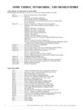
Transcription of NATIONAL BOARD INSPECTION CODE • PART 2 — …
1 Section VIII, Div. 1 (Rules for Construction of pressure Vessels).b) American Society of Mechanical Engi-neers: 1) ASME Section V (Nondestructive Exami-nation)2) ASME Section IX (Welding and Brazing Qualifications).c) code of Federal Regulations, Title 49, Parts 100 through 185, ) American Petroleum Institute API 579, Fitness for ) ADR 2003, European Agreement Concern-ing the International Carriage of Dangerous Goods by Road. (Published by the UN Eco-nomic Commission for Europe, Informa-tion Service, Palais des Nations, C7-1211 Geneve, Suisse).f) CGA , Cleaning Equipment for Oxygen ) CGA , pressure Relief Device Stan-dard, part 2: Cargo and Portable Tanks for Compressed Gases.
2 (Published by the Com-pressed Gas Association, Inc. [CGA], 4221 Walney Road, Chantilly, VA 20151).h) IMDG code 2002, International Maritime Dangerous Goods code (including Amend-ment 31-02. (Published by the International Maritime Organization [IMO], 4 Albert Embankment, London, SE1 7SR).i) RID 2003, Carriage of Dangerous Goods. (Published by the Intergovernmental Orga-nization for International Carriage by Rail [OTIF], Gyphenhubeliweg 30, C7-3006 Berne, Suisse).j) United Nations Recommendations on the Transport of Dangerous Goods Modal Regulations. (Published by the United Na-tions Publications, 2 UN Plaza, New York, New York 10017).
3 K) SSPC Publication #91-12, Coating and Lining INSPECTION Manual. (Published by Steel Structures Painting Council, 4400 Fifth Avenue, Pittsburgh, PA 15212-2683). conclusiona) During any continued service inspections or tests of transport tanks, performed by the Registered Inspector, the actual operating and maintenance requirements as speci-fied in this appendix shall be satisfied. The Registered Inspector shall determine, based on the applicable requirements of the code of Federal Regulations, Title 49, Parts 100 through 185, and this appendix, whether the transport tank can continue to be safely ) Defects or deficiencies in the condition, operation, and maintenance requirements of the transport tank, including piping, valves, fittings, etc.
4 , shall be discussed with the owner or user of the transport tank at the time of INSPECTION . Defects or deficiencies shall be corrected using the appropriate methods prior to returning the transport tank to Personnel safetY anD INSPECTION activities a) Proper INSPECTION of transport tanks may require pre- INSPECTION planning. This plan-ning should include development of an in-spection plan that will satisfy the applicable technical requirements of this part , the 213 NATIONAL BOARD INSPECTION code part 2 INSPECTIONcc. soft spots when the hose is under pressure , or any loose outer covering on the hose;dd.
5 Damaged, slipping, or excessively worn hose couplings;ee. loose or missing bolts or fastenings on the bolted hose coupling assembly;ff. Stainless steel flexible connectors with damaged reinforcement braid;gg. Internal self-closing stop valves that fail to close or that permit leakage through the valve detect-able without the use of instruments;hh. Pipes or joints that are severely neW or rePlaceD DeliverY Hose assembliesThe operator shall repair hose assemblies and place the cargo tank back inservice if retested successfully in accordance with the following:a) The new and/or replaced hose assembly is tested at a minimum of 120% of the hose s MAWP;b) The operator shall visually examine the delivery hose assembly while its under pressure ;c) If the test is successful, the operator shall assure that the delivery hose assembly is permanently marked with the month and year of the test.
6 D) It should be noted that after July 1, 2000, the operator shall complete a record docu-menting the test and INSPECTION , which shall include the following:1) The date and signature of the Inspector that performed the INSPECTION ;2) The owner of the hose assembly;3) The hose identification number;4) The date of the original delivery of the hose assembly and tests;5) Notes of any defects observed;6) Any repairs that may have been made; and7) Identification in the written report that the delivery hose assembly passed or failed the tests and tHicKness testinga) Thickness testing of the head and shell of unlined cargo tanks used for the transporta-tion of materials corrosive to the cargo tank shall be measured at least once every two ) Cargo tanks measuring less than the sum of the minimum prescribed thickness in Tables or , as applicable, plus one-fifth of the original corrosion allow-ance shall be tested testing criteriaThe testing criterion that shall be used for these requirements are as follows.
7 A) The measuring device shall be capable of accurately measuring thickness to within of an inch;231 NATIONAL BOARD INSPECTION code part 2 INSPECTION table -aminimum thickness for Headsmaterialsvolume capacity in liter per mm of length (gallons per inch of length)14 ( ) or lessOver 14 to 23 ( to )Over 23 ( )MSHSLASSALMSHSLASSALMSHSLASSALT hickness,mm (in.) (.100) (.100).160 ( ).115 ( ).155 ( ).173 ( ).129 ( ).129 ( ).187 ( ) table thickness for shells, in. (mm)cargo tank motor vehicle rated capacity in liters (gallons)msss/HslaalMore than 0 to at least 4,500 (0 to 17,000) ( ) ( ) ( )More than 4,500 to at least 8,000 (17,000 to 30,300) ( ) ( ) ( )More than 8,000 to at least 14,000 (30,300 to 53,000) ( ) ( ) ( )More than 14,000 (53,000) ( ) ( ) ( )Note.
8 The maximum distance between bulkhead, baffles, or ring stiffeners shall not exceed 1,525 mm (60 inches)bulkheads and baffles when used as tank reinforcement that is based on the volume capacity in gallons per l per mm (inch) of length for MC 406 cargo tanks constructed out of Mild Steel (MS), High Strength Low Alloy Steel (HSLA), Austenitic Stainless Steel (SS), or Aluminum (AL).e) Table specifies the minimum thickness requirements for shell based on the cargo tank motor vehicle rated ca-pacity in gallons when the cargo tank is constructed out of Mild Steel (MS), High Strength Low Alloy Steel (HSLA), Austenitic Stainless Steel (SS), or Aluminum (AL).
9 The thickness requirements in these tables are specified in decimal of a mm (inch) after Dot 407 cargo tanKs a) It is required that the type of materials used for DOT 407 cargo tanks, depending on the type of media being transferred be either Mild Steel (MS), High Strength Low Alloy Steel (HSLA), Austenitic Stainless Steel (SS), or ) The minimum required thickness of materi-als specified in Table for DOT 407 cargo tanks, when the minimum thick-ness requirements are based on the volume capacity in Liters l per sq mm (gallons) per square mm (inch) for the cargo tank s heads, or bulkheads and baffles, when these items are used for reinforcement purposes.
10 All thicknesses are expressed in decimals of a mm (inch) after ) The minimum required thickness of materi-als specified in Table for DOT 407 cargo tanks, when the minimum thick-ness requirements are based on the volume capacity in Liters l per sq. mm (gallons) per square mm (inch) for the cargo tank shell. All thicknesses are expressed in decimals of a mm (inch) after BOARD INSPECTION code part 2 INSPECTION table thickness for Heads (Dot 407), mm (in.)volume capacity sq. mm(in in. l/)10 ( )or lessover 10 to 14 ( to )over 14 to 18( to )over 18 to 22( to )over 22 to 26( to )over 26 to 30( to )over 30 ( )Thickness (MS) ( ) ( ) ( ) ( ) ( ) ( ) ( )Thickness (HSLA) ( ) ( ) ( ) ( ) ( ) ( ) ( )Thickness (SS) ( ) ( ) ( ) ( ) ( ) ( ) ( )Thickness (A) ( ) ( ) ( ) ( ) ( ) ( ) ( )table thickness for shells (Dot 407), mm (in.