Transcription of National CAD Standards for Drawing Set Hierarchy
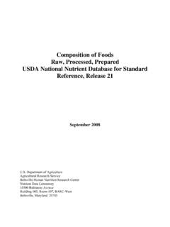
1 1 CEE 4333 CEE 4333 Fall 2005 Fall 2005 Planning and Organizing a CEE Drawing : What Planning and Organizing a CEE Drawing : What goes into a Drawing sets for a CEE Project?goes into a Drawing sets for a CEE Project?Components of a CEE Drawing Set Group exercise: Consider drawings of a structure. What kind of structure is it? What different systems will be constructed as part of this project: foundations, telecommunications, structures, mechanical, electrical, etc. What drawings do you have? What drawings are missing? How are the drawings organized? How do you know what page to look on for information about a particular component? National CAD Standards for Creating Drawing Sets CAD Layer Guidelines (AIA): Organization of Drawing sets & list of layers that may be included Format for naming layers in CAD Plotting Guidelines (US CADD/GIS Tech. Center) Color in AutoCAD file, plotted line width & plotted color The Construction Specification Institute Drawing set organization Drawing sheet organization Schedule organization Drafting conventions Terms and Abbreviations Symbols Set HierarchyO - OPERATIONSZ - CONTRACTOR/SHOP DRAWINGSX - OTHER DISCIPLINESR - RESOURCET - TELECOMMUNICATIONSE - ELECTRICALM - MECHANICALD - PROCESSP -PLUMBINGF - FIRE PROTECTIONQ - EQUIPMENTI - INTERIORSA - ARCHITECTURALS - STRUCTURALL - LANDSCAPEW CIVIL WORKSC CIVILB GEOTECHNICALV SURVEY/MAPPINGH HAZARDOUS MATERIALSG - GENERAL Cover SheetStandard Sheet IdentificationStandard Sheet Identification discipline designator sheet type designator sheet sequence number user-defined designatorA = alphabetical characterN = numerical characterU = user-definedA AN N N U U U Discipline DesignatorsA A N N N U U USheet Type DesignatorA A N N N U U USheet Sequence NumberA A N N NU U UUser-Defined DesignatorSheet Org.
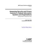
2 : Discipline DesignatorA - N N NLevel 1 Discipline Designator OnlyGGeneralFFire ProtectionHHazardous MaterialsPPlumbingVSurvey/MappingDProces sBGeotechnicalMMechanicalWCivil WorksEElectricalCCivilTTelecommunication sLLandscapeRResourcesSStructural XOther DisciplinesAArchitecturalZContractor / Shop DrawingsIInteriorOOperationsQEquipmentA A N N NLevel 2 Discipline Designator w/modifier characterDesignator Description ContentA Architectural Any or allASArchitectural Site Site PlanADArchitectural Demolition Protection & RemovalAI Architectural Interiors Interior Finishes2 Sheet Org.: Sheet Type DesignatorA A N N N0 General (symbols legend, notes, etc.)1 Plans (horizontal views)2 Elevations (vertical views)3 Sections (sectional views)4 Large Scale Views (plans, elevations, sections)5 Details6 Schedules and Diagrams7 User Defined8 User Defined9 3D Representations (isometrics, perspectives, photographs)Sheet Org.
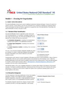
3 : Sheet Sequence NumberA A N N NThe sheet sequence number identifies each sheet in a series of the same discipline and sheet first sheet of each series is numbered 01, followed by 02 through Org.: User-Defined DesignatorsA A N N N U U UExamples - Supplemental DrawingsA - 1 0 2 R 1 (partially revised floor plan)A - 1 0 2 X 1 (totally revised floor plan)A - 1 0 2 A 1 (Phase 1 of a sequenced construction floor plan)Sample Typical Drawing SetSheet Sheet TitleG-001 Cover SheetA-001 Notes and SymbolsA-101 Floor PlanA-102 Reflected Ceiling PlanA-103 Roof PlanA-201 Exterior ElevationsA-301 Building SectionsA-302 Wall SectionsA-401 Enlarged Toilet PlanA-501 DetailsA-601 Room Finish ScheduleA-602 Door & Window SchedulesUDS establishes organization and provides consistency among disciplines. Thus, a floor plan may be located and identified as:S - 101 Structural First Floor PlanA - 101 Architectural First Floor PlanM - 101 Mechanical First Floor PlanE - 101 Electrical First Floor PlanDrawing Set ConsistencyAIA CAD Layer GuidelinesN-SMID-LLUF-LLAW-IADiscipline DesignatorMajor GroupMinor Group 1 Minor Group 2 StatusCAD Layer Name: Discipline DesignatorN-SMID-LLUF-LLAW-IAAA -Level 1 Discipline Designator GGeneralFFire ProtectionHHazardous MaterialsPPlumbingVSurvey/MappingDProces sBGeotechnicalMMechanicalWCivil WorksEElectricalCCivilTTelecommunication sLLandscapeRResourcesSStructural XOther DisciplinesAArchitecturalZContractor / Shop DrawingsIInteriorOOperationsQEquipmentAA -Level 2 - modifier characterDesignator Description ContentA Architectural Any or allASArchitectural Site Site PlanADArchitectural Demo.
4 Protection & RemovalAI Architectural Interiors Interior FinishesAs for Drawing Numbering3 CAD Layer Name: Major GroupN-SMID-LLUF-LLAW-IAThe mandatory Major Group field is a four-character field that identifies a major building system. The prescribed Major Group field codes (four-character abbreviations) show on the Layer List are logically grouped with specific discipline designators. However, any Major Group may be combined with any prescribed Discipline Designator, provided that the definition of the Major Group remains unchanged. User-defined Major Group field codes are notpermitted. Examples:V* - BLDG - *Surveying / mapping buildings and primary structuresV* - POWR - *Surveying / mapping powerB* - BORE - *Geotechnical - boringsC* - DRIV - *Civil drivewaysS* - BEAM - *Structural beamsS* - FNDN - *Structural foundationsA* - DOOR - *Architectural doorsAI WALL - * Architectural Interior wallsCAD Layer Name: Minor GroupsN-SMID-LLUF-LLAW-IAThe optional Minor Group fields are four-character fields that provide further clarification of information contained on a layer.
5 The prescribed Minor Group field codes (four-character abbreviations) show on the Layer List are logically grouped with specific discipline designators. However, any Major Group may be combined with any prescribed Discipline Designator, provided that the definition of the Major Group remains unchanged. User-defined Minor Group field codes are permitted. Examples:V* - BLDG - DECKS urveying / mapping buildings - outdoor decksV* - POWR - MHOLS urveying / mapping power - manholesB* - BORE - FDTAG eotechnical borings field dataC* - DRIV - FLNE - SIGNC ivil driveways fire lane pavement markingsS* - BEAM - STELS tructural beams - steelS* - FNDN - PIERS tructural foundations drilled piersA* - DOOR - FULLA rchitectural doors full heightAI WALL - FIRE Architectural Interior walls fire wallCAD Layer Name: StatusN-SMID-LLUF-LLAW-IAThe optional Status field is a one-character field that distinguishes the data contained on the layer according to the status of the work or the construction phase.
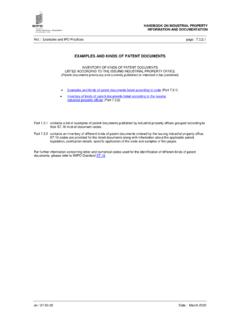
6 The prescribed field codes are as follows:NNew workEExisting to remainDExisting to demolishFFuture workTTemporary workMItems to be movedXNot in contract1-9 Phase numbersOrganizing Drawing Information Structure for identifying spaces, objects, components Reference Symbols Notes General Reference Keynotes Sheet KeynotesIdentifying Spaces, Objects ComponentsMultiple Views The CEE Perspective""5B5A123456798 ABDCB55DA55C14" X 20" EXTERIORCONCRETE COLUMN,TYPICALTWO-WAYSLAB, , '-1"20'-10"20'-1"62'-8"8 BAYS AT 18'-9" = 150'-0"18" X 18" INTERIORCONCRETE COLUMN,TYPICAL10-" THICK CONCRETE SLABSECOND FLOOR FRAMING PLAN159'-1034"8-" BRICK WALLBELOW1-" COMPRESSIBLE JOINTMATERIAL, TYPICALN20'-1"20'-10"20'-1"62'-8"DCAB8 BAYS AT 18'-9" = 150'-0"12345678918" X 18" INTERIORCONCRETE COLUMN,TYPICAL812-" THICK CONCRETE SLAB14" X 20" EXTERIORCONCRETE COLUMN,TYPICALD5 TYPICAL FLOOR FRAMING PLAN159'-1034"N4 Multiple Views The CEE Perspective987654321 NORTH PERIMETER FRAME ELEVATIONROOF7TH FLOOR6TH FLOOR5TH FLOOR4TH FLOOR3RD FLOOR2ND FLOOR1ST FLOOR65'-812"30"14" "2212" " BRICK WALLPARTIAL BRICK WALL8 BAYS AT 18'-9" = 150'-0"08"OPENCANOPY8'-8"8'-812"8'-812"8 '-812"8'-812"8'-812"13'-6"12'-312"3'-314 "3'-314"2'-412"3'-412"19'-6"08'-934"9'-1 114"HORIZONTAL LINES FOR STRAPS EA.
7 SIDE16 GA. STUDS FOR MOUNTING SIGNSPENTHOUSE ROOF14'-818"SOUTH PERIMETER FRAME ELEVATION8 BAYS AT 18'-9" = 150'09'-1114"3'-314"3'-314"3'-412"2'-412 "12'-312"19'-6"14" PLASTERCONCRETECOLUMNSCONCRETESPANDRELSC EMENT PLASTERWINDOWS13'-6"8'-812"8'-812"8'-812 "8'-812"8'-812"8'-8"65'-812"7TH FLOOR1ST FLOOR2ND FLOOR3RD FLOOR4TH FLOOR5TH FLOOR6TH FLOORROOF8'-934"HORIZONTAL LINES FOR STRAPS EA. SIDE16 GA. STUDS FOR MOUNTING SIGNS14'-818"20'-5"20'-1"20'-10"13'-6"22 '-212"30'-11"39'-712"48'-4"57'-012"65'-8 12"80'-458"7TH FLOOR8'-8"WEST PERIMETER FRAME ELEVATION1ST FLOOR13'-6"8'-812"8'-812"8'-812"8'-812"8 '-812"2ND FLOOR3RD FLOOR5TH FLOOR4TH FLOOR6TH FLOOR20'-1"20'-1"ACB20'-10"DROOFPENTHOUS E ROOF14'-818"19'-6"""5'-1012"FRAME FORHOTEL SIGN19'-7"30'-11"13'-6"22'-212"48'-4"39' -712"57'-012"80'-458"65'-812"ROOF7TH FLOOR6TH FLOOR5TH FLOOR4TH FLOOR3RD FLOOR2ND FLOOR1ST FLOOR8'-8"8'-812"8'-812"8'-812"8'-812"8' -812"13'-6"20'-1"20'-10"20'-1"CEMENT PLASTERPENTHOUSE ROOF14'-818"19'-6"12'-2"ABCDEAST PERIMETER FRAME ELEVATIONR eference SymbolsReference Symbols.
8 Examples from Skilling Ward Magnusson PlanNumber IdentificationSheet NumberKey Plan IndicatorLetter denotes Building Section or ElevationRevision Indicatorcloud area ofrevisionRemark IndicatorG General NotesD Demolition NotesR Remodel NotesS Site NotesExisting BuildingGridNew BuildingGridDetailLetter IdentificationSheet NumberWall SectionLetter IdentificationSheet NumberBuilding SectionLetter IdentificationSheet NumberBuilding ElevationLetter IdentificationSheet NumberMultiple Views The CEE Perspective""5B5A123456798 ABDCB55DA55C14" X 20" EXTERIORCONCRETE COLUMN,TYPICALTWO-WAYSLAB, , '-1"20'-10"20'-1"62'-8"8 BAYS AT 18'-9" = 150'-0"18" X 18" INTERIORCONCRETE COLUMN,TYPICAL10-" THICK CONCRETE SLABSECOND FLOOR FRAMING PLAN159'-1034"8-" BRICK WALLBELOW1-" COMPRESSIBLE JOINTMATERIAL, TYPICALN20'-1"20'-10"20'-1"62'-8"DCAB8 BAYS AT 18'-9" = 150'-0"12345678918" X 18" INTERIORCONCRETE COLUMN,TYPICAL812-" THICK CONCRETE SLAB14" X 20" EXTERIORCONCRETE COLUMN,TYPICALD5 TYPICAL FLOOR FRAMING PLAN159'-1034"NSection Views The CEE Perspective""22"2212"30"ROOFTYP.
9 FLOOR2ND FLOOR14" TYPICAL LONGITUDINAL SPANDRELSA TYPICAL TRANSVERSE SPANDRELSB TYPICAL COLUMN DETAILD2" clear (typ.)to vertical bar2"3"2"Lap 24 bar interior column; lap 36 bar dia. for exterior column,minimum 24" (typ.)12"max12"maxslope 1:6 @ 3"CSECTION OF BRICK WALL34" clear (typ.)2" clear22"4"1'-4"2" clear2212"30"2ND FLOORROOFTYP. FLOOR2"varies24" lap1 - #4#4 @ 24" BARS1 - #4 "4"8" BRICK4 - #4 JOINT MATERIALCONT. L 3 x 3 x 31612" CLEAR2" CLEAR2'-6"1"9"12"4"1'-4"10" SLAB13'-6" Drawing Roads5 Drawing RoadsDrawing Structural Steel ComponentsDrawing RC Structural ComponentsNotesReference Keynotes:Masterformatfor specifications (CSI)ElectricalMechanicalConveying SystemsSpecial ConstructionFurnishingsEquipmentSpecialt iesFinishesSpecification161514131211109 DivisionDoors and Windows8 Thermal and Moisture Protection7 Wood and Plastics6 Metals5 Masonry4 Concrete3 Sitework2 General Keynotes6 Sheet Keynotes