Transcription of NAU8814 Mono Audio Codec with Speaker Driver - Nuvoton
1 NAU8810. Differential/Mono Audio Codec with 2-wire Interface Control Interface emPowerAudio . 1. GENERAL DESCRIPTION. The NAU8810 a cost effective low power wideband Monophonic Audio Codec . It is suitable for a wide range of Audio applications, including voice telephony. Supported functions include a 5-band Graphic Equalizer, Automatic Level Control (ALC) with noise gate, PGA, standard I2S or PCM Audio interface, optional PCM time slot assignment, and a full fractional-N on-chip PLL. This device includes one differential microphone input, and multiple variable gain control stages in the Audio paths. Both a Mono headset/line-level output and a high power differential BTL Speaker Driver output are provided. The analog input path includes a PGA enabling dynamic range optimization of a wide range of input sources with programmable gain from -12dB to + In addition to a digital high pass filter to remove DC offset voltages, the ADC also features programmable voice band digital filtering.
2 Audio data is communicated via the Audio interface that supports multiple I2S and PCM data formats. The DAC converter path includes filtering, and mixing, programmable-gain amplifiers, and soft muting. The 2-Wire digital control interface has an independent supply voltage to enable easy integration into multiple supply voltage systems. The NAU88U10 operates at supply voltages from to , and the digital core can operate at a voltage as low as to conserve power. The NAU8810 is specified for operation from -40 C to +85 C, and is available with automotive AEC-Q100. qualification. Please refer to ordering information for AEC-Q100 compliance part number. 2. FEATURES. 24-bit signal processing linear Audio Codec . Audio DAC: 93dB SNR and -84dB THD. Audio ADC: 91dB SNR and -79dB THD.
3 Support variable sample rates from 8 - 48kHz Analog I/O. Integrated programmable Microphone Amplifier Integrated BTL Speaker Driver 1 W (8 / 5V). Earphone / Speaker / Line-Output Mixing / Routing Integrated Headset Driver 40mW (16 / ). Low Noise bias supply voltage for microphone On-chip full fractional-N PLL. Interfaces I2S digital interface PCM time slot assignment 2-Wire serial control Interface (I2C style; /Write capable). emPowerAudio . Datasheet Revision Page 1 of 102 March 1, 2017. NAU8810. Low Power, Low Voltage Analog Supply: to Digital Supply: to Nominal Operating Voltage: Additional features 5-band Graphic Equalizer Programmable ALC. ADC Notch Filter Programmable High Pass Filter Digital ADC/DAC Passthrough Mono data output on both channels Automotive AEC-Q100 grade 3 & TS16949 qualification, tested to a higher reliability standard Temperature: 40 C to +85 C.
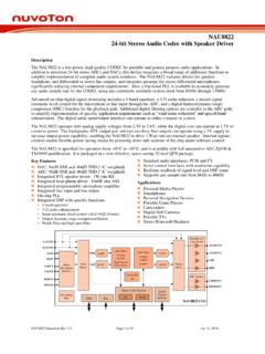
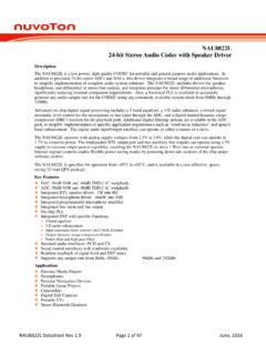
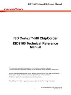
4 Applications All types of wired/wireless telephony Security Systems Mobile Telephone Hands-free Kits Residential & Consumer Intercoms ADC Filter MOUT. Input Volume DAC Filter MIC- Control Volume Microphone Mixers & Output ADC DAC. Interface Gain HPF Control Mixers MIC+ Stage Notch Limiter Filter SPKOUT+. -1 SPKOUT- Microphone Digital Audio Interface Control IF. MICBIAS. Bias I2S PCM 2-wire Audio I/O Digital I/O. emPowerAudio . Datasheet Revision Page 2 of 102 March 1, 2017. NAU8810. 3. PIN CONFIGURATION. SPKOUT - VDDSPK. VREF. MIC+. MIC- 20. 19. 18. 17. 16. MICBIAS 1 15 VSSSPK. VDDA 2 14 SPKOUT+. VSSA 3 13 MOUT. VDDD 4 12 SDIO. VSSD 5 11 SCLK. 10. 6. 7. 8. 9. MCLK. BCLK. DACIN. FS. ADCOUT. Metal Paddle (VSSA). Figure 1: 20-Pin QFN Package emPowerAudio.
5 Datasheet Revision Page 3 of 102 March 1, 2017. NAU8810. 4. PIN DESCRIPTION. Pin Name 24-Pin Functionality A/D Pin Type MICBIAS 1 Microphone Bias A O. VDDA 2 Analog Supply A I. VSSA 3 Analog Ground A O. VDDD 4 Digital Supply D I. VSSD 5 Digital Ground D O. ADCOUT 6 Digital Audio Data Output D O. DACIN 7 Digital Audio Data Input D I. FS 8 Frame Sync D I/O. BCLK 9 Bit Clock D I/O. MCLK 10 Master Clock D I. SCLK 11 2-Wire Serial Clock D I. SDIO 12 2-Wire I/O D O. MOUT 13 MONO Output A O. SPKOUT+ 14 Speaker Positive Output A O. VSSSPK 15 Speaker Ground A O. SPKOUT- 16 Speaker Negative Output A O. VDDSPK 17 Speaker Supply A I. VREF 18 Decoupling internal analog mid supply reference A O. MIC- 19 Microphone voltage Negative Input A I. MIC+ 20 Microphone Positive Input A I.
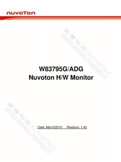
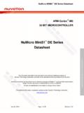
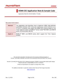
6 Table 1: Pin Description Notes 1. The 20-QFN package includes a bulk ground connection pad on the underside of the chip. This bulk ground should be thermally tied to the PCB, and electrically tied to the analog ground. 2. Unused analog input pins should be left as no-connection. 3. Any unused digital input pin must be tied high or low as appropriate. emPowerAudio . Datasheet Revision Page 4 of 102 March 1, 2017. 5. emPowerAudio . BLOCK DIAGRAM. Datasheet Revision VSSA. VSSSPK. VDDSPK. VDDA. VSSD. VSSD. DACMOUT[0] MOUTMXEN[3]. (0x38) (0x03). PGAEN[2] MOUTBST[3]. (0x02) (0x31). BYPMOUT[1] MOUT. (0x38). -12 dB to + dB. PGABST[8]. HPF. MIC- (0x2F). NMICPGA[1]. (0x2C) ALC. ADC LIMITER DAC. PGAMT[6] SPKMOUT[x:0]. (0x2D) NOTCH (0xxx). PGAGAIN PMICBSTGAIN[6:4].
7 (0x2F). FILTER. (0x2D). VREF. PMICPGA. MIC+ SPKGAIN[5:0]. PMICBSTGAIN[6:4] SPKBST[2]. DACSPK[0] (0x36) (0x31). (0x2F) = 000. (0X32). Page 5 of 102. SPKOUT+. MICROPHONE. MICBIAS BIAS. MICBIASEN[4] BYPSPK[1]. (0x2F) (0x32) (Sidetone) BYPASS SPKMXEN[2] SPKOUT- (0x03). VDDA. R. CONTROL. VREF DIGITAL Audio INTERFACE PLL. INTERFACE. Figure 2: NAU88U10 General Block Diagram R. FS. SDIO. SCLK. BCLK. MCLK. DACIN. ADCOUT. March 1, 2017. NAU8810. NAU8810. 6. Table of Contents 1. GENERAL DESCRIPTION ..1. 2. FEATURES ..1. 3. PIN CONFIGURATION ..3. 4. PIN DESCRIPTION ..4. 5. BLOCK 6. TABLE OF CONTENTS ..6. 7. LIST OF FIGURES ..9. 8. LIST OF TABLES ..11. 9. ABSOLUTE MAXIMUM RATINGS ..12. 10. OPERATING CONDITIONS ..12. 11. ELECTRICAL 12. FUNCTIONAL DESCRIPTION.
8 17. INPUT PATH ..17. The differential microphone input (MIC- & MIC+ pins)..17. Positive Microphone Input (MIC+) ..18. Negative Microphone Input (MIC-) ..19. PGA Gain Control ..19. PGA Boost / Mixer Stage ..20. MICROPHONE BIASING ..21. ADC DIGITAL FILTER BLOCK ..22. Programmable High Pass Filter (HPF) ..23. Programmable Notch Filter (NF) ..24. Digital ADC Gain Control ..24. PROGRAMMABLE GAIN AMPLIFIER (PGA)..25. Automatic level control (ALC) ..25. Normal Mode ..28. ALC Hold Time (Normal mode Only) ..28. Peak Limiter Mode ..29. Attack Time ..30. Decay Times ..30. Noise gate (normal mode only) ..30. Zero Crossing ..31. DAC DIGITAL FILTER BLOCK ..32. Hi-Fi DAC De-Emphasis and Gain Control ..34. Digital DAC Output Peak Limiter ..34. Volume Boost ..34.
9 5-Band Equalizer ..35. ANALOG OUTPUTS ..36. Speaker Mixer Outputs ..36. Mono Mixer Output ..37. Differential Output Configuration ..38. Unused Analog I/O ..38. GENERAL PURPOSE Slow Timer Clock ..41. emPowerAudio . Datasheet Revision Page 6 of 102 March 1, 2017. NAU8810. CLOCK GENERATION BLOCK ..41. CONTROL INTERFACE ..45. 2-WIRE Serial Control (I2C Style Interface) ..45. 2-WIRE Protocol Convention ..45. 2-WIRE Write Operation ..46. 2-WIRE Operation ..46. DIGITAL Audio Right Justified Audio data ..48. Left Justified Audio data ..49. I2S Audio data ..50. PCM Audio data ..51. PCM Time Slot Audio data ..52. Companding ..53. POWER SUPPLY ..54. Power-On Reset ..54. Power Related Software Considerations ..54. Software Reset ..55. Power Up/Down Sequencing.
10 55. Reference Impedance (REFIMP) and Analog Bias ..57. Power Saving ..57. Estimated Supply Currents ..57. 13. REGISTER DESCRIPTION ..59. SOFTWARE RESET ..61. POWER MANAGEMENT REGISTERS ..61. Power Management 1 ..61. Power Management 2 ..62. Power Management 3 ..62. Audio CONTROL REGISTERS ..62. Audio Interface Control ..62. Audio Interface Companding Clock Control Register ..64. Audio Sample Rate Control DAC Control Register ..65. DAC Gain Control Register ..66. ADC Control Register ..66. ADC Gain Control Register ..67. 5-BAND EQUALIZER CONTROL REGISTERS ..68. DIGITAL TO ANALOG CONVERTER (DAC) LIMITER REGISTERS ..69. NOTCH FILTER REGISTERS ..70. AUTOMATIC LEVEL CONTROL REGISTER ..71. ALC1 REGISTER ..71. ALC2 REGISTER ..72. ALC3 REGISTER ..73. NOISE GAIN CONTROL REGISTER.