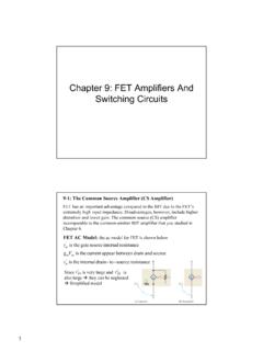
Transcription of NCP81074 - Single Channel 10A High Speed Low-Side …
1 Semiconductor Components Industries, LLC, 2015 November, 2015 Rev. 31 Publication Order Number: NCP81074 /DNCP81074A, NCP81074 BSingle Channel 10A HighSpeed Low-Side MOSFETD riverThe NCP81074 is a Single Channel , low side MOSFET driver. It iscapable of providing large peak currents into capacitive loads. Thisdriver can deliver a 7 A peak current at the Miller plateau region tohelp reduce the Miller effect during MOSFETs switching exhibits a split output configuration allowing the user to control theturn on and turn off slew rates. This part is available in SOIC 8 andDFN8 2x2 mm High Current Drive Capability 10 A TTL/CMOS Compatible Inputs Independent of Supply Voltage High Reverse Current Capability (10 A) Peak 4 ns Typical Rise and 4 ns Typical Fall Times with nF Load Fast Propagation Delay Times of 15 ns with Input Falling and 15 nswith Input Rising Input Voltage Range from V to 20 V Split Output Configuration Dual Input Design Offering Drive Flexibility These Devices are Pb Free, Halogen Free/BFR Free and are RoHSCompliantApplications Server Power Telecommunication, Datacenter Power Synchronous Rectifier switch Mode Power Supply DC/DC Converter Power Factor Correction Motor Drive Renewable Energy, Solar InverterDFN8MN SUFFIXCASE 506 AAMARKINGDIAGRAMSXXMGG11 XXXXXXAYWW G18 SOIC 8 CASE 75118 XXXXXX = Specific Device CodeA= Assembly LocationY= YearWW= Work WeekG= Pb Free PackageSee detailed ordering.
2 Marking and shipping information onpage 2 of this data = Specific Device CodeM= Date CodeG= Pb Free Device(Note: Microdot may be in either location)NCP81074A, INFORMATION DeviceTemperatureRange (5C)MarkingInput TypePackage TypeShipping NCP81074 AMNTBG 40 to +140 CLFixed Digital ThresholdDFN8 2x2(Pb Free)3000 / Tape & ReelNCP81074 BMNTBG 40 to +140 CMVDD Based ThresholdDFN8 2x2(Pb Free)3000 / Tape & ReelNCP81074 ADR2G 40 to +140 NCP81074 AFixed Digital ThresholdSOIC 8(Pb Free)2500 / Tape & ReelNCP81074 BDR2G 40 to +140 NCP81074 BVDD Based ThresholdSOIC 8(Pb Free)2500 / Tape & Reel For information on tape and reel specifications, including part orientation and tape sizes, please refer to our Tape and Reel PackagingSpecifications Brochure, BRD8011 DIAGRAMF igure 1.
3 NCP81074 Block DiagramNCP81074A, DESCRIPTIONPin +Non Inverting Input which has logic compatible threshold and hysteresis. If not used, this pin should beconnected to either VDD or GND. It should not be left ground. This ground should be connected very closely to the source of the power ground. This ground should be connected very closely to the source of the power pin. Connect to Gate of Pin. Connect to Gate of Supply Input supply Input Inverting Input which has logic compatible threshold and hysteresis. If not used, this pin should be connect-ed to either VDD or GND. It should not be left unconnectedFigure 2. TYPICAL APPLICATION CIRCUITABSOLUTE MAXIMUM RATINGSP arameterValueUnitMinMaxSupply VoltageVDD Current (DC) Current (Pulse<1 ms)10 AOutput Current (Pulse< ms)Iout_pulse10 AInput VoltageIN+, IN 624 VOutput VoltagesOUTH, OUTL + Voltages (Pulse< ms)OUTH, OUTL + Operation TemperatureTJ 40150 CStorage TemperatureTstg 65160 Electrostatic DischargeHuman body model, HBM4000 VCharge device model, CDM1000 OUT Latch up Protection500mAMoisture Sensitivity Level (MSL)MSL1 Stresses exceeding those listed in the Maximum Ratings table may damage the device.
4 If any of these limits are exceeded, device functionalityshould not be assumed, damage may occur and reliability may be , OPERATING CONDITIONSP arameterRatingUnitVDD supply to 20 VIN+, IN input voltages 5 to 20 VJunction Temperature Range 40 to +140 CFunctional operation above the stresses listed in the Recommended Operating Ranges is not implied. Extended exposure to stresses beyondthe Recommended Operating Ranges limits may affect device 1. THERMAL INFORMATIONP ackageTheta JA (5C/W)Theta JC (5C/W)DFN 8 811550 Table 2. ELECTRICAL CHARACTERISTICS (Note 1) (Typical values: VDD =12V, 1uF from VDD to GND,TA = TJ = 405C to 1405C, typical at TAMB = 255C, unless otherwise specified)ParameterSYMBOLTest ConditionsMINTYPMAXUnitSUPPLY VOLTAGEVDD Under Voltage Lockout (rising)VCCRVDD Under Voltage Lockout (Falling)VCCFVDD Under Voltage Lockout (hysteresis)VCCH300mVOperating Current (no switching) Under Voltage Lockout to OutputDelay (Note 1)VDD rising10msINPUTSNCP81074A High ThresholdVthHInput rising from logic Low ThresholdVthLInput falling from logic High ThresholdVthHInput rising from logic low(VDD = 8 V to 12 V)VDD Low ThresholdVthLInput falling from logic high(VDD = 8 V to 12 V)
5 GND+ + + Pull up ResistorRin 200kWIN+ Pull Down ResistorRin+200kWOUTPUTSO utput Resistance HighROHIOUT = 10 Resistance LowROLIOUT = +10 Source Current(2)ISourceOUT = GND200 ns Pulse10 AMiller Plateau Source Current(2)ISourceOUT = V200 ns Pulse7 APeak Sink Current(2)ISinkOUT = VDD200 ns Pulse10 AMiller Plateau Sink Current(2)ISinkOUT = V200 ns Pulse7 ANCP81074A, 2. ELECTRICAL CHARACTERISTICS (Note 1) (Typical values: VDD =12V, 1uF from VDD to GND,TA = TJ = 405C to 1405C, typical at TAMB = 255C, unless otherwise specified)ParameterUnitMAXTYPMINTest ConditionsSYMBOLSWITCHING CHARACTERISTICSP ropagation Delay Time Low to High, INRising (IN to OUT) (Note 2)td1 CLoad = nF1527nsPropagation Delay Time High to Low, INFalling (IN to OUT) (Note 2)td2 CLoad = nF1527nsRise Time (Note 2)trCLoad = nF47nsFall Time (Note 2)tfCLoad = nF47nsProduct parametric performance is indicated in the Electrical Characteristics for the listed test conditions, unless otherwise noted.
6 Productperformance may not be indicated by the Electrical Characteristics if operated under different All Limits are 100% tested at TAMB = 25 C and guaranteed across temperature by design and statistical Guaranteed by characterization. *See timing 3. LOGIC TRUTH TABLEIN+IN OUTHOUTLOUT(OUTH & OUTL CONNECTEDTOGETHER)LLHIGH ZLLLHHIGH ZLLHLHHIGH ZHHHHIGH ZLLF igure 3. Non inverting Input Driver OperationFigure 4. Inverting Input Driver OperationNCP81074A, CHARACTERISTICSF igure 5. Supply Current vs. SwitchingFrequency, VDD = 12 VFigure 6. Supply Current vs. SwitchingFrequency, VDD = VSWITCHING FREQUENCY (kHz)SWITCHING FREQUENCY (kHz)20001400120010008006002000050100150 2002502000140012001000800400200001030406 07090100 Figure 7. Fall Time vs. TemperatureCLOAD = nFFigure 8.
7 Rise Time vs. TemperatureCload = nFTEMPERATURE ( C)TEMPERATURE ( C)14010080600 20 40 20 9. Propagation Delay TD1 vs. SupplyVoltageFigure 10. Propagation Delay TD2 vs. SupplyVoltageVDD, SUPPLY VOLTAGE (V)VDD, SUPPLY VOLTAGE (V)2016141210864101112131416171820181412 1086478101112131516 SUPPLY CURRENT (mA)SUPPLY CURRENT (mA)FALL TIME (nS)RISE TIME (nS)TD1, DELAY TIME (nS)TD2, DELAY TIME (nS)400180016006001600 180020508010 nF470 pF1 nF10 nF470 pF1 V15 V5 V10 V12010020 4020 V15 V5 V10 = 1 nFCLOAD = nFCLOAD = nFCLOAD = 10 nFCLOAD = 1 nFCLOAD = nFCLOAD = nFCLOAD = 10 nF16914 NCP81074A, CHARACTERISTICSF igure 11. Supply Current vs. Supply VoltageCLOAD = nFFigure 12. Supply Current vs. Supply VoltageCLOAD = nFSUPPLY VOLTAGE (V)SUPPLY VOLTAGE (V)2018161410864020608012014018020020161 412108640206080120140180200 Figure 13.
8 Reverse Current, PMOS(on), PMOS(off)Figure 14. Reverse Current, PMOS(off), PMOS(on)OUT H VDD (V)OUT L (V) 15. Supply Current vs. Supply VoltageSUPPLY VOLTAGE (V) CURRENT (mA)SUPPLY CURRENT (mA)OUTPUT CURRENT (A)OUTPUT CURRENT (A)SUPPLY CURRENT (A)124010016018401001602 MHz1 MHz10 Test Conditions:TJ = 25 C1 ms Positive PulseFsw = 1 kHzTest Conditions:TJ = 25 C1 ms Positive PulseFsw = 1 = VDDIN+ = VDDGND and VDDNCP81074A, WAVEFORMS Non Inverting InputFigure 16. Rise Time with nF LoadFigure 17. Fall Time with nF LoadFigure 18. Propagation Delays with nF LoadFigure 19. Propagation Delays with nF LoadNCP81074A, WAVEFORMS Inverting InputFigure 20. Rise Time with nF LoadFigure 21. Fall Time with nF LoadFigure 22. Propagation Delays with nF LoadFigure 23.
9 Propagation Delays with nF LoadNCP81074A, LAYOUT RECOMMENDATIONP roper component placement is extremely important inhigh current, fast switching applications to provideappropriate device operation and design robustness. TheNCP81074 gate driver exhibits a powerful output stageenabling large peak currents with fast rise and fall the NCP81074 provides a split outputconfiguration for slew rate control, a proper PCB layout iscrucial to ensure maximum performance. The followingcircuit layout guidelines are strongly recommended whendesigning with the NCP81074 . Place the driver close to the power MOSFET in order tohave a low impedance path between the output pins andthe gate. Keep the traces short and wide to minimize theparasitic inductance and accommodate for high peakcurrents.
10 Place the decoupling capacitor close to the gate driveIC. Placing the VDD capacitor close to the pin andground improves noise filtering. This capacitor supplieshigh peak currents during the turn on transition of theMOSFET. Using a low ESL chip capacitor is highlyrecommended. Keep a tight turn on turn off current loop paths tominimize parastic inductance. High di/dt will inducevoltage spikes on the output pin and the MOSFET the source and return signals taking advantageof flux cancellation. Since the NCP81074 is a 2x2mm package driving highpeak currents into capacitive loads, adding a shieldingground plane helps in power dissipation and noiseblocking. The ground plane should not be a currentcarrying path to any of the current loops. Any unused pin, should be pulled to either raildepending on the functionality of the pin to avoid anymalfunction on the output.