Transcription of Near Vertical Incidence Sky Wave (NVIS).ppt - N3UJJ
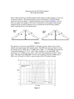
1 Near Vertical Incidence Sky Wave ( nvis )PropagationPropagation Marc C. Tarplee, N4 UFPB ackground Near Vertical Incidence Sky Wave ( nvis ) propagationprovides local and regional coverage on the lower HFbands. nvis isnotnew. nvis isnotnew. German army experimented with nvis during WW II US military personnel used nvis in Vietnam. Many amateurs have used nvis on 80 and 160mwithout knowing nvis works RF is launched at a high elevation angle (> 70 degrees). If the frequency of the RF is below the critical frequency, itwill be refracted back towards the earth s surface. Because the RF is launched at a nearly Vertical angle, itreturns to earth close (1 300 mi) to the transmitter Attenuation on nvis paths is less than DX paths becausethe RF takes the shortest possible trip through theionosphere s highly absorbing D layerNVIS Propagation PathHow nvis works In order for the nvis signal to be returned to theearth s surface, its frequency must be less than thecritical frequency of the F-layer Duringdaytime,thecriticalfrequencyisappr oximately Duringdaytime,thecriticalfrequencyisappr oximately5 to 15 MHz.
2 After sunset, the critical frequency dropsthroughout the night, reaching a low of 1 to 5 MHz justbefore dawn. It is desirable to use frequencies just below the criticalfrequency to minimize signal absorption by the D-layerBand Selection for nvis Periods of high solar activity Daytime - 60, 40 and 30 m Nighttime 60 and 80 m Periodsoflowsolaractivity Periodsoflowsolaractivity Daytime - 80, 60 or 40m Nighttime - 80 or 160 mAdvantages of nvis Elimination of the Skip Zone nvis provides good coverage between the outer limit of groundwave propagation (25 miles) and the inner limit of normal skywave return (300 miles).
3 Wave return (300 miles). Noise Reduction nvis antennas look directly into outer space and mostastronomical objects are not powerful emitters in the lower HFregion Terrestrial noise sources are not in the field of view of the antennaand do not contribute significantly to received Applications Emergency Communications Reliable nvis communications are possible out to distances ofapproximately 300 miles Small number of nvis stations are required to provide a statewidenetwork. Amateurs can quickly establish communications using nvis after Amateurs can quickly establish communications using nvis aftera natural disaster because nvis uses readily available HFequipment and simple antennas.
4 nvis is adaptable. CW, SSB and various HF digital modes such asPSK-31 all can be used with nvis Traffic Nets nvis eliminates the skip zone, permitting smoother traffichandlingNVIS Operation Prior planning is important - an nvis net must havefrequency agility. The Net Manager and Net Control Stations should determine theoperating frequencies that will be used at various times of the dayoperating frequencies that will be used at various times of the day Procedures for frequency hopping must be agreed on beforehand,so that stations are not lost as the net moves from band to band Practice before the emergency is mandatory!
5 Sample nvis Net Frequency PlanSC Region 2 nvis Net Frequency PlanWinter Plan, SSB NetsLocal Time of NetOperating Frequency(1-5)0001 0800 Primary: MHz Alternate: MHz0801 1600 Primary: MHz Alternate: MHz1601 2000 Primary: MHz Alternate: MHz2001 2400 Primary: MHz Alternate: MHzSummer Plan, SSB NetsLocal Time of NetOperating Frequency(1-5)0001 0800 Primary: MHz Alternate: MHz0801 1600 Primary: MHz Alternate: MHz1601 2400 Primary: MHz Alternate: MHzSample nvis Net Frequency PlanSC Region 2 nvis Net Frequency PlanOperating Notes(1)If primary frequency cannot support nvis , the net will move to the alternate frequency for thetime period in which the net is operating.
6 If the alternate frequency cannot support nvis , the netwill move to the alternate frequency of the next later time period, if it is lower than the currentalternate frequency. If the alternate frequency of the later time period is not lower, use thealternate frequency from the adjacent earlier time period, if it is lower. If a lower alternatealternate frequency from the adjacent earlier time period, if it is lower. If a lower alternatefrequency cannot be found, the net must be moved to VHF.(2)Band changes will occur at quarter hour intervals.(3)All operating frequencies, other than those in the 60m band, may vary by +/- 10 KHz to avoidinterference.
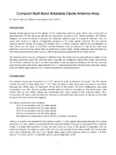
7 (4)Output power on 60m must be limited to 50 W PEP.(5)Only USB is allowed on 60 mAssembling an nvis Station A standard 100W HF transceiver will work just fine forNVIS The key element of an nvis station is the antenna. It must be designed to radiate at very high takeoff angles. Generally, existing amateur antenna systems, with the exception ofmost 160 m dipoles, do not radiate in the proper direction forNVIS operationNVIS Dipoles Mounted at a height between and . Takeoff angle is 90 deg. Antenna height below can cause problems Rapid decrease in gain below (3 dB loss at ) Rapid decrease in gain below (3 dB loss at ) Decrease in feed point impedance below Antenna may be erected as an inverted-vee with onlyone support Max height should be less than People should be kept away from the ends of the antennaNVIS Dipoles Gain and Takeoff AngleConstruction of nvis Dipoles Use copper or aluminum wire #14 THHN stranded wire available in 500-foot rolls for ~ $15.
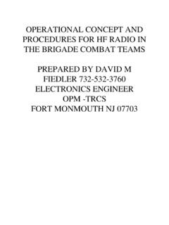
8 #17 Aluminum fence wire - available in quarter-mile roles for ~$14,$14, nvis dipole lengthsfl475 BandDipole Length160 ( MHz)250 ft80 ( MHz)121 ft 10 in60 ( MHz)88 ft 5 in40 ( MHz)65 ft 11 inMultiband Operation with NVISD ipoles Dipole should be fed with ladder line Antenna must be less than high at the highestoperating frequency. Radiation pattern of an 80m nvis dipole ft above ground the fundamental frequencyNVIS Loop Antennas 1 loop antenna can also be used for nvis operation Twopossiblearrangements Twopossiblearrangements It can be mounted horizontally close to the ground andthe feed point can be anyplace along the loop.
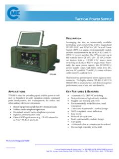
9 3supports needed It can be mounted vertically with the bottom wire closeto ground and fed to produce horizontally polarizedRF. 1 support neededHorizontal nvis Loop Should be at a height of to < , Gain drops off quickly at heights below . Input impedance is 70 140 ohms over average Operation with a HorizontalNVIS Loop The loop should be fed with ladder line The loop must be less than high at the highestoperating frequency. Operation is possible from to approximately Radiation Pattern of an 80m Horizontal nvis loop ft above groundtimesthefundamentalfrequencyVertic al nvis Loop Generally a delta loop is mounted on a single support Apex height is approximately high, Bottom wire raised approximately above the ground.
10 Takeoff angle is 90 degrees Input Impedance is 100- 140 ohmsMultiband Operation with a VerticalNVIS Loop The loop should be fed with ladder line The loop must be less than high at the highestoperating frequency. Operation is possible from to approximately Pattern of an 80 m Vertical nvis Loop ft above groundtimesthefundamentalfrequencyMobile /Portable Antennas for nvis Inverted L made by bending a mobile whip antennaover the roof of a vehicle. Short dipole made by combining 2 loaded fiberglasswhipantennasdesignedforvehicle usewhipantennasdesignedforvehicleuse Any metal object that is parallel to the ground and notmore than 10 15 feet above it.