Transcription of Need for an industry standard for ESD valves from ...
1 1 Need for an industry standard for ESD valves from engineering and safety point of view Meghdut Manna, Mr. I&C and Reliability Engineer Tahakum, Abu Dhabi UAE, Middle East February, 2005 Key words ESD valves (Emergency Shutdown Valve), SIS (Safety Instrumented System), SIF (Safety Instrumented Function), Test Interval (TI), Maximum shut off Differential Pressure (Max. shut off DP), CAPEX (Capital Expenditure), Partial stroking, PFDavg (Probability of Failure on Demand), Dynamic Torque, Torque Safety Margin, PHA (Process Hazard Analysis), HAZOP (HAzard and OPerability study ), FMEDA (Failure Mode Effect and Diagnostics Analysis) Abstract Since the Piper Alpha disaster in the North Sea, design of ESD valves has been given top priority and remains to be of great concern for plant safety management.
2 Constant improvements have been made to ensure the integrity of the ESD valves . Essentially, ESD valves should perform their duty (usually closure of valves ) under plant demand condition. To meet the production bottom-line, these valves are required to remain open for months, even years, which leads to build up or corrosion in the valve internals. Final control element is the weakest link in the SIS. It contributes 50% of total PFDavg for a SIF. To meet the desired Availability figure for ESD valves , different tools have been devised. Partial Valve Stroke Test, Valve Actuator signature curve, Testing Intervals (TI) are buzzwords in the industry .
3 However, there is no industry standard for ESD valves which covers both engineering and safety aspects together. Design aspects of ESD valves and associated actuators vary from operator to operator and sometimes from one asset to another for the same operator. This article is an attempt to address the need for a common industry standard for ESD valves . Introduction Selection of maximum shut off DP for ESD valve torque calculation and associated actuator sizing sometimes become subject for debate during the design stage. Too much conservative value leads to oversized actuator and increased CAPEX. Furthermore, there is not a standard guideline for the selection of the valve safety factor amongst the valve/actuator manufacturer (service factor) and actuator-valve torque safety margin.
4 Many valve manufacturers utilize their own safety contingency in addition to the user s specification. As per the study, final control element contributes 50% to the SIS failure. Special care should be given while designing the ESD valves . However, ESD valves should not be oversized. 2 With the introduction of SIS, Partial Stroke , valve/actuator signature facilities, questions may be raised whether high design contingency is still required to cater the life time torque requirement. Essentially, all put together, elevates the CAPEX. This paper addresses the following: Basis of maximum DP selection from process application and recommendation for a suitable maximum DP for SIS application Cost analysis at different shut off DP & different actuator-valve torque safety margin Type of actuator mechanism to be fitted with the valve Dynamic torque specifications Valve opening & closing time -design and safety concern Safety valve on the actuator supply line - weakest link in actuator circuit Partial stroke testing , Valve-Actuator signature curve, Test Interval (TI)
5 Valve-Actuator assembly PFDavg and SIL levels ESD valve leakage, fire test specification Miscellaneous design issues Basis of maximum DP selection from process application and recommendation for a suitable maximum DP for SIS application Sizing of an ESD valve actuator becomes a very easy task for an actuator manufacturer if all the necessary information is made available from the valve manufacturer. Valve torque is a function of maximum shut off DP. There is no standard guideline for deriving the maximum differential pressure for actuator sizing. In practice, philosophy varies from operator to operator, from one asset to another for a particular operator, and widely varies from one design consultant to another.
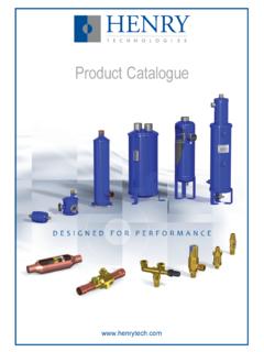
6 Essentially, this happens because of lack of proper analysis during the design stage. In many instances, ESD valve engineers tend to take conservative values instead of analyzing individual cases. Proper PHA can lead to optimum selection of maximum DP. In general, the philosophies listed below are being followed for sizing DP Maximum DP under operational conditions Maximum DP at the upstream failure conditions Design Pressure of the line Cold Flange rating of the line Statistical Failure DataFinal Cont rol El e m e n t 50%Logic Solver 8%Sensor 42% 3 It has been common practice for some of the operators or design contractors to follow only one philosophy for all the on/off valves (ESD valves and On-Off valves for general service) irrespective of the service and application which leads over design of actuators.
7 Line Design Pressure as sizing maximum DP In absence of proper analysis, line design pressure is considered as standard sizing criteria, despite the large margin between safety valve set point and the design pressure. Some of the operators prefer to adopt this philosophy for all valves for service interchangeability. With same line design pressure and flange rating, these valves can be interchanged for service purposes. For example, valve for a production well can be interchanged with an injection well, whenever required. Or, the same valve can be utilized to other assets in similar applications. However, some applications demand design pressure as the sizing DP because of the process requirement where safety valve set pressure is close to the design pressure.
8 Cold Flange Rating Pressure as sizing maximum DP Some operators prefer that all valve torque calculations should be done based on the cold flange rating pressure service interchangeability reasons. With this assumption, design contractors tend to specify the torque requirement for all the ESD valves and associated actuator based on the cold flange rating. This type of trivial specification will increase the CAPEX. It is also possible that during the design stage, both operator and design contractor have looked into the possibility of how many valves might be interchangeable. Interchangeability of valves between different assets may not be cost effective. Dismantling and transportation costs may be higher than a new valve, although other factors should be considered such as emergency and delivery conditions.
9 It must be stated that there is no available data from any operator on how many valves have been interchanged from one asset to another during their sites operations history. Case Study for Maximum DP Selection Process HAZOP approach Sizing DP for valve and actuator is not generally taken into discussion during conventional process HAZOP because this is purely a design related issue. However, a simplified safety analysis may justify the selection of the maximum DP. Let us analyze a simple case study: Consider the separator inlet node of a wellhead. In this example, the original production well is being utilized as gas lift well by installing a new ESD valve.
10 Here, normal operating pressure is much less than the well shut in pressure and design pressure. 4 Line Size: 10 , Line Rating: ANSI 1500# RTJ Maximum operating pressure: 10 barg High Pressure Alarm setting: 14 barg Safety valve setting: 18 barg. Well shut in pressure: 176 barg. Line / Vessel Design Pressure: 228 barg. Cold Flange rating pressure (@ 1500#): 259 barg Minimum Air Supply Pressure: 5 barg Maximum Air Supply Pressure : barg Line design pressure was considered as sizing DP (228 barg) for valve torque calculation. To justify the basis, consider one upset condition (High Pressure on the well flow line) for which ESD valve is required to be closed.