Transcription of NETGEAR ProSAFE 24-Port Gigabit Smart Managed Switch …
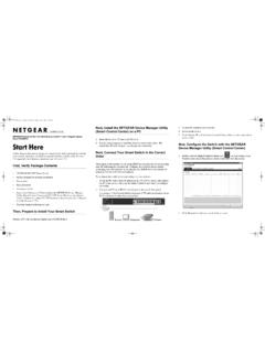
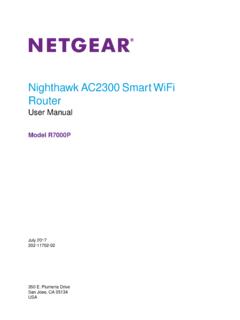
1 3. Power on the Switch and wait two minutes. Configure the Switch With a Static IP Address Switch Note: If your network uses a DHCP server, this section does not apply. Go directly to Connect the Switch to a Network. Installation Network If you are using static IP addresses in your network, configure the Switch IP. address before you connect the Switch to a network. Internet 1. Configure a computer with a static IP address in the subnet. PoE access points ProSAFE 24-Port Gigabit Smart Managed Switch 2. Plug the Switch into a power outlet and connect your computer to the PoE VoIP phone Switch using an Ethernet cable. With PoE+ and 2 SFP Ports 3. Open a web browser and enter in the address bar. Sample connections GS724 TPv2 The default IP address of the Switch is Check the PoE Status A login page displays. 4. Enter password for the password. The Switch can supply up to 30W PoE+ (IEEE ) to each port, with a maximum PoE power budget of 190W across all active PoE+ ports.
2 The System Information page displays. 5. Select System > Management > IP Configuration. The PoE Max LED indicates the status of the PoE budget on the Switch : The IP Configuration page displays. Off. Sufficient (more than 7W of) PoE power is available. 6. Select the Static IP Address radio button. Solid amber. Less than 7W of PoE power is available. 7. Enter the static IP address, subnet mask, and default gateway IP address Blinking amber. At least once during the previous two minutes, less than that you want to assign to the Switch . 7W of PoE power was available. 8. Click the Apply button. Your settings are saved. Configure the Switch Package Contents Connect the Switch to a Network You can configure the Switch either by using a computer's web browser or by installing the Smart Control Center Utility (see Smart Control Center Utility) on 1. Connect PoE (or non-PoE) devices to the RJ-45 PoE network ports on the Switch front panel. your Windows-based computer.
3 NETGEAR ProSAFE 24-Port Gigabit Smart Managed Switch GS724 TPv2. Use Category 5e (Cat 5e) Ethernet cables terminated with RJ-45. AC power cord (localized to country of sale) connectors to make Gigabit connections. Web Browser Access Rubber footpads for tabletop installation 1. For initial configuration, open a web browser on a computer that is on the 2. Connect an RJ-45 port or SFP port on the Switch to a network that same network and subnet as the Switch and enter the Switch 's IP address. 19-inch rack-mount kit for rack installation includes a DHCP server. If you are unsure how to determine the IP address of the Switch , you can Note: In a small office or home office network, connect the Switch to the use the Smart Control Center Utility. Resource CD LAN port of a router that, in turn, is connected to an Internet modem. A login page displays. Installation guide If you use an SFP port, you must insert an SFP transceiver module, which is 2. Enter password for the password.
4 Available from NETGEAR . The System Information page displays. Configure the Switch With the Smart Control Center Troubleshooting Tips 3. Configure the Switch for your network. Utility For information about Switch configuration, see the user manual for your Here are some tips for correcting simple problems that might occur: Switch , which you can download from 1. Connect the computer to the network. The computer that is running the Smart Control Center Utility must be Be sure to power on your computer and Switch in the following sequence: on the same network (with same broadcast domain) as the Switch . Smart Control Center Utility 1. Turn on the Switch and wait two minutes. 2. Double-click the Smart Control Center icon. 2. Turn on the computer and connect it to the Switch . The Smart Control Center Utility runs on Windows-based computers. The utility is on the resource CD that came with the Switch . You can also visit The Smart Control Center displays.
5 Make sure that the network settings for the computer or device are to download the utility. correct. You might need to temporarily turn off the antivirus program, 3. Click the Discover button. firewall, or both on the computer so that the utility can discover the Switch . Install the Smart Control Center Utility From the CD The Smart Control Center Utility finds Smart Managed Switches on the To use the Smart Control Center Utility, you must configure your network and displays each Switch 's MAC address, IP address, and model Note: The Smart Control Center Utility requires Adobe Air. If Adobe Air computer's security software to allow broadcast UDP packets to go through number. is not detected during Smart Control Center Utility installation, you are to the destination IP address of The Smart Control prompted to allow Adobe Air to be installed. If the utility does not discover your Switch , verify that the cable Center Utility uses UDP source and destination ports 63323 and 63324.
6 Connections are secure and that the computer's IP address is in the same 1. Insert the resource CD into a computer that is on the same network and Make sure that the Ethernet cables are plugged in correctly. For each PoE. subnet as the Switch , and click the Discover button. the same subnet as the Switch . device connected to the Switch , the corresponding lower port LED on the 2. Click the Smart Control Center Utility link and follow the prompts to You might need to temporarily turn off the antivirus program, firewall, or Switch lights solid green. (The LEDs are located to the left of the ports.) If install the program. both on the computer so that the utility can discover the Switch . the corresponding lower port LED lights solid amber, a PoE fault occurred. The utility is installed in the program directory of your computer and a 4. Select the Switch that you want to configure. Make sure that the PoE Max LED is off. If the PoE Max LED is solid amber, Smart Control Center icon is placed on your desktop.
7 5. Click the Web Browser Access button. disconnect one or more PoE devices to prevent PoE oversubscription. Note: If the Resource CD Center does not automatically launch, open 6. When prompted, enter the password. Windows Explorer, locate the CD content, right-click the Autostart file, The default password is password. Support and then select Run as Administrator. 7. Click the Login button. Thank you for selecting NETGEAR products. You can visit 3. If prompted, allow Adobe Air to be installed. to register your product, get help, access the latest The System Information page displays. Note: For optimal discovery performance, we recommend that you restart downloads and user manuals, and join our community. We recommend that you your computer after installing the Smart Control Center Utility. 8. Configure the Switch for your network. use only official NETGEAR support resources. For information about Switch configuration, see the user manual for your For the current EU Declaration of Conformity, visit Switch , which you can download from 9.
8 When you are finished with the configuration, return the computer's For regulatory compliance information, visit antivirus program and firewall to their usual settings. See the regulatory compliance document before connecting the power supply. NETGEAR INT LTD NETGEAR , Inc. NETGEAR , Inc., NETGEAR and the NETGEAR Logo Building 3 University Technology Centre 350 East Plumeria Drive are trademarks of NETGEAR , Inc. Any non NETGEAR . Curraheen Road Cork Ireland trademarks are used for reference purposes only. San Jose, CA 95134, USA March 2017.