Transcription of New Cooling Channel Design for Injection Moulding - IAENG
1 Abstract Injection Moulding is one of the most versatile and important operation for mass production of plastic parts. In this process, Cooling system Design is very important as it largely determines the cycle time. A good Cooling system Design can reduce cycle time and achieve dimensional stability of the part. This paper describes a new square sectioned conformal Cooling Channel system for Injection Moulding dies. Both simulation and experimental verification have been done with these new Cooling channels system. Comparative analysis has been done for an industrial part, a plastic bowel, with conventional Cooling channels using the Moldflow simulation software. Experimental verification has been done for a test plastic part with mini Injection Moulding machine.
2 Comparative results are presented based on temperature distribution on mould surface and Cooling time or freezing time of the plastic part. The results provide a uniform temperature distribution with reduced freezing time and hence reduction in cycle time for the plastic part. Index Terms Conformal Cooling Channel , Cycle time Moldflow, Square shape. I. INTRODUCTION Injection Moulding is a widely used manufacturing process in the production of plastic parts [1]. The basic principle of Injection Moulding is that a solid polymer is molten and injected into a cavity inside a mould which is then cooled and the part is ejected from the machine. Therefore the main phases in an Injection Moulding process involve filling, Cooling and ejection. The cost-effectiveness of the process is mainly dependent on the time spent on the Moulding cycle in which the Cooling phase is the most significant step.
3 Time spent on Cooling cycle determines the rate at which parts are produced. Since, in most modern industries, time and costs are strongly linked, the longer is the time to produce parts the more are the costs. A reduction in the time spent on Cooling the part would drastically increase the production rate as well as reduce costs. So it is important to understand and optimize the heat transfer process within a typical Moulding process. The rate of the heat exchange between the injected plastic and the mould is a decisive factor in the economical performance of an Injection mould A B M Saifullah is a research doctoral student at Industrial Research Institute Swinburne (IRIS), Swinburne University of Technology, Melbourne, Australia (e-mail- also Member, IAENG . S. H. Masood is a Professor of Mechanical & Manufacturing Engineering at Faculty of Engineering and Industrial Sciences, Swinburne University of Technology, Melbourne, Australia.)
4 (Corresponding author, ph:+61-3-9214 8260, fax: +61-3-9214 5050, e-mail: Dr Igor Sbarski is a Senior Lecturer at Faculty of Engineering and Industrial Sciences, Swinburne University of Technology, Melbourne, Australia.(e-mail: )..Heat has to be taken away from the plastic material until a stable state has been reached, which permits demolding. The time needed to accomplish this is called Cooling time or freezing time of the part. Proper Design of Cooling system is necessary for optimum heat transfer process between the melted plastic material and the mould. Traditionally, this has been achieved by creating several straight holes inside the mould core and cavity and then forcing a Cooling fluid ( water) to circulate and conduct the excess heat away from the molten plastic. The methods used for producing these holes rely on the conventional machining process such as straight drilling, which is incapable of producing complicated contour-like channels or anything vaguely in 3D space.)
5 An alternative method of Cooling system that conforms or fits to the shape of the cavity and core of the mould can provide better heat transfer in Injection Moulding process, and hence can result in optimum cycle time. This alternative method uses contour-like channels of different cross-section, constructed as close as possible to the surface of the mould to increase the heat absorption away from the molten plastic. This ensures that the part is cooled uniformly as well as more efficiently. Now-a-days, with the advent of rapid prototyping technology such as Direct Metal Deposition (DMD), Direct Metal Laser Sintering (DMLS) and many advanced computer aided engineering (CAE) software, more efficient Cooling channels can be designed and manufactured in the mould with many complex layout and cross-sections[2,3,4].
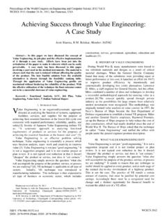
6 This paper presents a square section conformal Cooling Channel (SSCCC) for Injection Moulding die. Simulation has been done for an industrial plastic part, a circular plastic bowel for these SSCCC and compared with conventional straight Cooling channels (CSCC) with Moldflow Plastic Inside (MPI) software. Comparative experimental verification has also been performed with SSCCC and CSCC die for a circular shape test part with mini Injection Moulding machine for two plastic materials. Result shows that SSCCC die gives better Cooling time and temperature distribution than that of CSCC dies. II. Design OF THE PART AND MOULDS A. Part Design The part circular plastic bowl made of polypropylene (PP) thermoplastic, as shown in Fig 1(a) has been designed with Pro-Engineer CAD software. It was then exported to IGES (Initial Graphics Exchange Specification) file surface model to import in MPI for analysis.
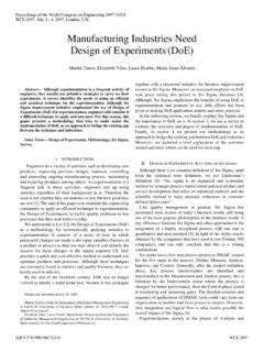
7 Material volume of the plastic part is and its weight is gm. Experimental test part as shown in Fig 1(b) has also been designed with Pro-Engineer software. Experimental New Cooling Channel Design for Injection Moulding A B M Saifullah, Masood and Igor Sbarski Proceedings of the World Congress on Engineering 2009 Vol IWCE 2009, July 1 - 3, 2009, London, : 978-988-17012-5-1 WCE 2009 verification has been done with two types of plastic materials, PP and ABS (Acrylonitrile Butadiene Styrene). Test part volume was cm3, and part weight for ABS and PP were gm and respectively. (a) (b) Fig-1 CAD model of (a) Circular plastic bowel, (b) Test part. B. Mould Design Mould Design has been done using Pro/Moldesign module of the Pro/Engineer system.
8 This mould is then manufactured with Computer Numerical Control (CNC) machine. The mould shown in Fig 2 has two parts, the core and the cavity. Square section conformal Cooling Channel (SSCCC) has been produced around the cavity by CNC machining of one half of the Channel on cavity part and the other half on the core part. Both halves are then joined with screws and sealed with liquid gasket (Permatex) to avoid water leakage. Fig-2 Assembly CAD model of mould with core (top) and two cavity parts. III. ANALYSIS AND RESULTS MPI simulation software has been used for part analysis [5]. Analysis sequence was flow-cool-warp. Polypropylene plastic material has been used for analysis. Comparative analysis has been done with conventional straight Cooling Channel (CSCC) and SSCCC.
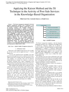
9 The diameter of CSCC was 12 mm and the length of SSCCC section size was 12 mm (Fig 3). Fusion meshing with global edge length of cm has been used. The numbers of mesh elements used were 12944 and 12291 for CSCC and SSCCC respectively. (a) (b) Fig-3 Analysis setting in MPI (a) CSCC (b) SSCCC Both cases used Cooling medium as normal water of 25 C. Reynolds number was 10000, melting temperature was 230 C. Comparative analysis result from MPI as shown in Fig 4 shows that SSCCC shows better temperature distribution and (a) (b) Fig-4 Comparative freezing or Cooling time (a) CSCC (b) SSCCC. less part freezing time than CSCC. In case of CSCC, most of the part cools in about 24 second except the top few areas, while on the other hand SSCCC diagram shows that it is less than 20 seconds.
10 And also CSCC shows the time to freeze range to be and SSCCC shows this to be So, using SSCCC, 5 second of Cooling time has been reduced which is 35% reduction of Cooling time. IV. EXPERIMENTAL VERIFICATION AND RESULTS Experimental verification has been done with a circular shape plastic test part using the machined mould as shown in Fig 5. Part diameter was 40 mm and thickness was 7 mm. The mould dimension was cm3. Mould material was mild steel. Experiment has been done with a mini (a) (b) Fig-5 (a) Mild steel Core (left) and cavity with SSCCC (b) CSCC of mild steel. Proceedings of the World Congress on Engineering 2009 Vol IWCE 2009, July 1 - 3, 2009, London, : 978-988-17012-5-1 WCE 2009 Injection Moulding machine of techsoft mini moulder (Fig 6).