Transcription of New measurement methods of focal spot size and …
1 18th World Conference on nondestructive Testing, 16-20 April 2012, Durban, South Africa New measurement methods of focal Spot Size and Shape of X-ray Tubes in Digital Radiological Applications in Comparison to Current Standards Klaus BAVENDIEK1, Uwe EWERT2, Adrian RIEDO3, Uwe HEIKE1, Uwe ZSCHERPEL2. 1. YXLON International GmbH, Hamburg, Germany, 2. BAM Federal Institute from Materials Research and Testing, Berlin, Germany, 3. COMET AG, Flamatt, Switzerland, Abstract Unsharpness in the image may reduce the visibility of details. Magnification is often required to achieve a spatial resolution similar to film technique, when using digital systems. A part of the unsharpness results from the focal spot size. To determine the effective focal spot size, thousands of images with different tubes, energies, magnifications and IQIs from different EN and ASTM standards were taken to evaluate the influence of the unsharpness in the digital image due to the focal spot.
2 This leads to reference values for the effective focal spot size of the different tubes. These reference values were compared with the values of the pin hole camera images according to EN 12543-2 and they deviated significantly. Several modifications of the evaluation method were proposed and a method with Integrated Line Profiles which produces results like an edge profile method was developed and tested providing similar results as the reference values. A second more simple method for end-users was introduced based on the evaluation of Penetrameter hole edges. A proposed update of the standards for focal spot measurements in ASTM and ISO is introduced. New classes will help the users to identify more simple and reliable the X-ray tube for their application.
3 Keywords: Non-destructive testing, radiography, X-ray tubes, focal spot size, standards, integrated line profile method (ILP). 1. Introduction The exact focal spot size is required for optimization of image quality in radiological testing. The current standards (EN 12543 and ASTM E 1165) describe different measurement methods , which do not provide identical values. In practice the operator needs to achieve a sufficient image quality. This depends among other factors on the total image unsharpness too. Both, the inherent detector unsharpness and the geometric unsharpness contribute to the total unsharpness. The geometric unsharpness is determined by the focal spot intensity distribution and the magnification used. Therefore, the shape of the focal spot cannot be neglected, even if the shape distribution is not required by any standard practice.
4 2. Shape of an X-ray focal spot The shape of an X-ray focal spot is formed by the filament, the target, the internal way of flight of the electrons and the target angle with the X-ray window. The classical X-ray tubes for exposure of films typically have large focal spots. The newer digital systems, with larger pixel sizes in comparison to film resolution, require magnification technique for resolution of small details. With magnification the focal spot shape and size become more important. The development of X-ray tubes with high dose power AND small focal spot leads to different focal spot shapes. The existing standards for measurement of focal spot shapes, like EN 12543 or ASTM E 1165, do not provide useful values, which could be used for the calculation of unsharpness in the radiological images, as required in ASTM E 2698 or ISO 17636-2.
5 Sometimes the values are significantly too large, sometimes the nominal focal spot values are too small because of side-wings in the focal spot. Beside CT applications four different main areas for the use of X-ray tubes can be identified: Figure 1. Different focal Spots of tubes for (A) film radiography (B) inspection of Automotive Castings (mini focus). (C) inspection of Aerospace & Welds (small mini focus). (D) -Focus tube Figure 2. Photograph and pin hole image of a burning focal Spot with low dose power of a high power X-ray tube for film radiography with large spot (see Fig. 1A). The X-ray tubes for film radiography typically have focal spot sizes of a few mm and power up to 5kW. focal spot sizes below 1 mm are used for radiography of light metal castings, mainly for automotive industry.
6 focal spots which are smaller than at tube power of < 1kW are used for aerospace castings and weld inspection. Finally -focus tubes have focal spots below 100 m. Its industrial use is mainly in the field of inspection of thin welds or in the semiconductor industry. Standards for measurement of focal spot size The measurement of the focal spot size is specified by the following standards today: EN 12543 Characteristics of focal spots in industrial X-ray systems for use in non-destructive testing Parts 1 to 5. Part 1: Scanning method (reference method, but no more equipment available). Part 2: Pinhole camera radiographic method (mainly used method for manufacturers). Part 3: Slit camera radiographic method Part 4: Edge method Part 5: measurement of the effective focal spot size of mini and micro focus X-ray tubes ASTM E1165 - Standard Test Method for measurement of focal Spots of Industrial X-Ray Tubes by Pinhole Imaging IEC 60336: Medical electrical equipment X-ray tube assemblies for medical diagnosis.
7 Characteristics of focal spots (Slit, Pin hole and Star methods ). These standards are not consistent; different methods lead to different values for the identical X-ray tube even in the same standard, if different parts are used. Figure 3. Different Values for identical focal Spots of 8 different X-ray tubes measured by EN12543-2 and -5. Using EN12543-2 the values are often up to a factor of 2 larger than measured with EN 12345-5. ASTM E1165 uses the same pinhole method as EN12543-2 but a different procedure for evaluation. Some of the focal spots do not fit to the evaluation method of the pin hole image. The new types of X-ray tubes for digital radiology require improved methods for measurement of the focal spot size. 3. measurement of Unsharpness in the Image due to the focal Spot Size The X-ray user usually does not need to consider the focal spot shape, only the unsharpness due to the focal spot size is of interest to the user.
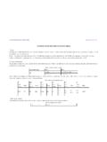
8 The total unsharpness in the image is measured with an edge method or by a duplex wire IQI as described in EN 462-5 or ASTM E 2002. It is required to know the total image unsharpness in several standards; in ASTM E 2698. Equation (1) (taken from ASTM E 2698) can be used for evaluation of the unsharpness due to the limited focal spot size: (1). (2). (3). (4). Applied to images from the performed experiments formula (5) fits better for measurement of the unsharpness due to the focal spot size than formula (4) (see also: Robert F. Wagner [1]). (5). The unsharpness in radiographic images was studied at YXLON with COMET and BAM as partners. Three different Image Quality Indicators (IQIs) were used with high and medium contrast known from different standards.
9 Figure 4. Used IQIs: (A) EN 462-5 (B) Edge of DW 1 of EN 461-5 (C) Plaque Hole IQI (D) Tungsten plate with holes (A) EN 462-5 duplex wire IQI was evaluated as given in ASTM E 2597 (20% dip evaluation). (B) From same IQI the wire 1 (800 m) was used as an edge target on both sides of the wire (C) Both sides of the 4T or 2T hole of a plaque hole type IQI were used as an edge (D) A 1mm Tungsten plate with several holes of diameter was used similar to (C). The edges from (B), (C), (D) were measured from 85% to 45% and on the other side from 45% to 85% (together 40% + 40% as required by EN 12543-5, but with shifted thresholds). The results were multiplied with the factor of to extrapolate from 80% to 100%. The evaluation procedures are based on the above mentioned standards with minor modifications.
10 Magnification was varied from up to 15. Four different energies were used: 90kV, 120kV, 180kV and 225kV. Nine different focal spots were measured with all the four IQIs; the sizes varied from 250 m to nominal size (EN 12543-2); the IQIs were placed exactly in the center of the beam. The detector was a PerkinElmer XRD 822 with a SRb of 230 m. Similar tests were done with a Thales FS 35 and Hamamatsu C 7942. For evaluation the YXLON software IMAGE 3500 was used; special software algorithm were added, for the unsharpness measurement of the holes (see Fig. 5 for example). Figure 5. Automated evaluation procedure with the Plaque Hole IQI in IMAGE 3500 using the hole diameter as reference A) Projection radiograph of an hole target with magnification. Due to the focal spot shape, the hole rim is blurred.