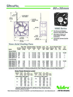
Transcription of Nidec UltraFlo Fan Options - nidecpg.com
1 Model Name SuffixSpeed-StableFree-RunningFansFans Description-01-51 No optional features: Color-coded power leads (red +, black -) with stripped Open-collector tachometer circuit, two square wave pulses per revolution, 50 per-cent duty cycle, terminated in a third lead wire. Standard lead wire color is Open-collector, non-latching, low-pass/high-fail locked rotor alarm circuit terminatedin a third lead wire. Standard lead wire color is Open-collector, low-pass/high-fail, trip-point alarm circuit terminated in a third leadwire; non-latching alarm is activated at specified low-speed threshold (70 percentof fan s nominal operating speed, standard). Standard lead wire color is Open-collector tachometer and non-latching, low-pass/high-fail locked rotor alarmcircuit terminated in a third lead wire;two square wave pulses per revolution, 50percent duty cycle, under no-fault conditions.
2 Standard lead wire color is Pulse-width modulated speed control circuit terminated in a third lead lead wire color is PWM speed control circuit (option -06 or -56) terminated in a third lead wire (stan-dard = blue) and an open-collector, tachometer (option -02 or -52) terminated in afourth lead wire (standard = yellow).-08-58 PWM speed control circuit (option -06 or -56) terminated in a third lead wire (stan-dard = blue) and an open-collector, non-latching, low-pass/high-fail locked rotoralarm circuit (option -03 or -53) terminated in a fourth lead wire (standard = yellow).-09-59 PWM speed control circuit (option -06 or -56) terminated in a third lead wire (stan-dard = blue) and an open-collector, non-latching, low-pass/high-fail, trip-point alarmcircuit (option -04 or -54) terminated in a fourth lead wire (standard = yellow).
3 -10-60 Thermal speed control circuit employs an NTC thermistor mounted on the housingof the fan;the speed control profile requires specification of low-temperature oper-ating speed (rpm), low-speed threshold ( C) and high-speed threshold ( C).-11-61 Thermal speed control circuit (option -10 or -60) and an open-collector tachometercircuit (option -02 or -52) terminated in a third lead wire (standard = yellow).-12-62 Thermal speed control circuit (option -10 or -60) and an open-collector, non-latch-ing, low-pass/high-fail locked rotor alarm circuit (option -03 or -53) terminated in athird lead wire (standard = yellow).-13-63 Thermal speed control circuit with pulse-width modulated speed control: Thermalcontrol profile, using an NTC thermistor mounted on the housing of the fan, can betuned to application requirements by PWMinput terminated in a third lead wire(standard = blue).
4 -14-64 Thermal speed control with PWM control (option -13 or -63) terminated in a thirdlead wire (standard = blue), and an open-collector, tachometer (option -02 or -52)terminated in a fourth lead wire (standard = yellow).-15-65 PWM speed control circuit (option -06 or -56) terminated in a third lead wire (stan-dard = blue) and an open-collector, non-latching, inverse (high-pass/low-fail) lockedrotor alarm circuit terminated in a fourth lead wire (standard = yellow). Options UltraFlo UltraFlo is a registered trademark of Nidec CorporationNidec America Corporation phone 781-848-0970 email FANVFANSIGNALICGNDXt1t2 t3t41 REVOLUTIONIC MAX = 10 mADUTY CYCLE = 50% 10%VFANVLOW(SEE GRAPH)PULL-UPRESISTOROPEN-COLLECTOR TACHOMETERDC FANVFANSIGNALGNDXVFANVLOW(SEE GRAPH)OKAYFAULTICIC MAX = 10 mANON-LATCHING ALARMPULL-UPRESISTOROPEN-COLLECTOR LOCKED ROTOR ALARMDC FANVFANSIGNALGNDXIC MAX = 10 mANON-LATCHING ALARMVFANVLOW(SEE GRAPH)OKAYFAULTICSPECIFIED LOW-SPEED THRESHOLD (rpm)STANDARD = 70% OF NOMINALPULL-UPRESISTOROPEN-COLLECTOR TRIP-POINT ALARMDC FANVFANSIGNALICGNDXt1t2 t3t41 REVOLUTIONOKAYIC MAX = 10 mA TACH DUTY CYCLE = 50% 10%)VFANVLOW(SEE GRAPH)FAULT(NON-LATCHING)
5 PULL-UPRESISTOROPEN-COLLECTOR TACH/LOCKED ROTOR ALARMDC FANVFANSIGNALICGNDXt1t2 t3t41 REVOLUTIONOKAYIC MAX = 10 mA TACH DUTY CYCLE = 50% 10%)VFANVLOW(SEE GRAPH)FAULT(NON-LATCHING)PULL-UPRESISTOR OPEN-COLLECTOR TACH/INVERSE LOCKED ROTOR ALARMTYPICAL VALUES OF VLOW AS A FUNCTION OF 10IC (mA)VWOL)V( FANVFANCONTROLGNDXVHIGH = to = to = DUTY s to ms PULSE-WIDTH MODULATED SPEED CONTROL020406080100 FULL SPEED1500 RPMPWM DUTY CYCLE (%)fxLLUF([ = 0051 + ]ELCYC YTUD )0051 - DEEPS TYPICAL PWM CONTROL PROFILEDC FANVFANGNDXNTCTHERMISTORA/DCUSTOMER-SPEC IFIED CRITERIA:LOW OPERATING SPEED (RPM)LOW-SPEED THRESHOLD ( C)HIGH-SPEED THRESHOLD ( C)THERMAL SPEED CONTROLTYPICAL THERMAL CONTROL PROFILE010203040506070 TEMPERATURE ( C)DEEPS FANVFANCONTROLGNDX5V30K 10K47 KttHIGH/t = DUTY s to ms NTCTHERMISTORA/DCUSTOMER-SPECIFIED CRITERIA:LOW FAN SPEED AT 100% DUTY CYCLE (RPM)LOW-SPEED THRESHOLD ( C)HIGH-SPEED THRESHOLD ( C)VHIGH = to = to SPEED CONTROLTYPICAL THERMAL/PWM CONTROL PROFILES010203040506070 TEMPERATURE ( C)DEEPS CYCLE = 80%DUTY CYCLE = 60%TUD%001 = ELCYC YNidec America Corporation phone 781-848-0970 email