Transcription of Nodal Analysis - Solved Problems
1 Nodal AnalysisYaz Z. Li, rights reserved. No part of this publication may be reproduced or trans-mitted, in any form or by any means, mechanical or electrical, includingphotocopying and recording or by any information storage and retrieval sys-tem, without permission in writing from the author of this publication have used his best efforts in preparing this publication. All Problems are solvedby hand to make sure that solutions are correct. All theories and methods are developed, researched andtested to determine their effectiveness. However, the author makes no warranty of any kind, expressed orimplied, with regard to solutions or documentations in this publication.
2 The author shall not be liable inany event for incidental or consequential damages related to, or arising out of, the furnishing, performance,or use of the topics, solutions, programs and Problems of this publication or materials referred to in developed in Japan, QR-Codes are two dimensional barcodes designed to havetheir contents decoded at a high speed with remarkable accuracy. QR Codes hold infor-mation such as Internet addresses (urls), Business Cards, Phone Number, Messages andso on. In thsi ebook, the QR codes of urls are posted beside the. Therefore, you can ac-cess those web pages by scanning their QR-codes by your mobile camera.
3 You may needan application to decode QR codes, Most modern phones comes with built-in QR almost all Problems , their PSpice schematics are provided in ourwebsite. These files are created by PSPICE Student 2010 ..5 Reference Node ..6 Node Voltages ..6 Nodal Analysis Steps ..10 Complicated Cases ..18 More Problems ..31 List of Figures1 Refrence Node Symbol ..62 Finding Node Voltages ..63 All Nodes ..74 Candidates For Reference Node ..75 The reference Node ..86 Node Voltages ..87 Voltage source between two nodes ..98 problem 1..119 problem 1 - All nodes ..1210 problem 1 - The reference node and node voltages.
4 1211 Preoblem 1 - PSpice simulation result ..1312 problem 2..1413 problem 2 - All nodes ..1414 problem 2 - The reference node and node voltages ..1515 problem 2 - Loop for KVL ..1616 Preoblem 2 - PSpice simulation result ..1717 problem 3..1918 problem 3 - All nodes ..1919 problem 3 -The reference node and node voltages ..2020 problem 3 - Applying KVL to find supernode voltage ..2021 problem 3 - Applying KVL to determineVy..2222 Preoblem 2 - PSpice simulation result ..2223 Preoblem 4 ..2324 Preoblem 4 - All nodes ..2525 Preoblem 4 - The reference node ..2626 Preoblem 4 - PSpice simulation result ..2727 Preoblem 5.
5 2828 Preoblem 5 - All nodes ..2829 Preoblem 5 - The reference node and node voltages ..2930 Preoblem 5 - PSpice simulation result ..3031 Preoblem 6 ..3132 Preoblem 6 - All nodes ..3233 Preoblem 6 - The reference node and node voltages ..3334 Preoblem 6 - PSpice simulation result ..3635 Preoblem 7 ..3736 Preoblem 7 - All nodes ..3837 Preoblem 7 - The reference node and node voltages ..3838 Preoblem 7 - The supernode..4039 Preoblem 7 - Current directions and voltage polarities forsources ..4140 Preoblem 7 - PSpice simulation result ..43 Nodal AnalysisIntroductionNodal Analysis is a systematic method to determine the voltageat each node relative to the reference node by repeatedly ap-plying KCL.
6 In Nodal Analysis , also called node-voltage analysisor branch-current method, the voltage between nodes is deter-mined in terms of the branch currents. In this method, a sys-tem of equations in which the unknowns are the voltages at theprincipal nodes of the circuit is set up and Solved . The set ofequations developed in the Nodal Analysis in fact represents anddescribes the circuit. After determining these Nodal voltages,the currents in the various branches of the circuit can be Nodal Analysis starts with selecting one of the nodes as thereference node. Since one of the nodes is selected as the refer-ence node, if there areNnodes in the circuit there will beN 1linearly independent equations in general.
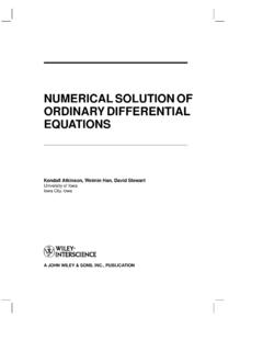
7 The solution of thisset of equations yields theN 1unknown node voltages. Thesenode voltages can be used with the Ohm s law to determine allcurrents in the Analysis - Reference NodeReference Nodesee comments, ask your circuits, we usually label a node as the reference node alsocalled ground and define the other node voltages with respectto this point. The reference node has a potential of0 Vby defi-nition. The symbol of reference node is depicted in Fig. 1 Refrence Node SymbolAs mentioned, the selection of the reference node is , a wise selection can make the solving easier. As a gen-eral rule, it is usually chosen to beNode Voltagessee comments, ask your voltage drop from a node to the reference node (ground) iscalled the node voltage.
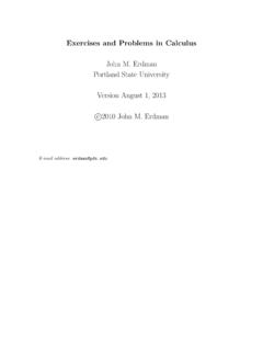
8 To keep definition simple, node volt-ages are usually defined with positive s find and label node voltages for the circuit shown in Fig. 2:R5R6+ 10VR1R2R4R3+ -5 VFig. 2 Finding Node VoltagesCopyright 2010 - Page 6 Nodal Analysis - Node VoltagesThe circuit has 5 nodes as shown in Fig. + 10VR1R2R4R3+ -5 VFig. 3 All Engineering Circuit Analy-sisby: J. David IrwinTwo of the nodes have 4 elements connected to them. These arethe best candidates to be reference + 10VR1R2R4R3+ -5 VFig. 4 Candidates For Reference NodeCopyright 2010 - Page 7 Nodal Analysis - Node VoltagesLet s choose one as the reference node (Fig. 5).R5R6+ 10VR1R2R4R3+ -5 VFig.
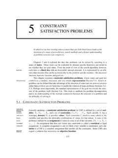
9 5 The reference NodeNow, we define node voltages for the remaining nodes as de-picted in Fig. 6. These node voltages represent the voltage be-tween the node and the + 10VR1R2R4R3+ -5VV4V3V2V1 Fig. 6 Node VoltagesCopyright 2010 - Page 8 Nodal Analysis - Node VoltagesWhen there is a voltage source between a node and the refer-ence node, the node voltage corresponds exactly to the voltageof the voltage source. In our example, we have two node volt-ages. The 5 Vvoltage source is placed between the referenceand the node labeled asV1. Therefore,V1= there is a voltage source between two nodes, the differencebetween the corresponding node voltages equals to the voltageof the source.
10 In our example, the10 Vvoltage source is locatedbetween nodes labeled byV2andV4. Therefore,V2 V4=10V. Itis important to note that voltage of the positive node minus theone of negative node is equal to the voltage of the source. KVLcan be used to show this:R5R6+ 10VR1R2R4R3+ -5VV4V3V2V1 Fig. 7 Voltage source between two nodesKVL around the loop: V2+(+10)+V4=0 V2 V4=10V. Re-call that the reference node is always defined to be the negativepolarity of all node 2010 - Page 9 Nodal Analysis - Nodal Analysis StepsNodal Analysis Stepssee comments, ask your Identify all nodes in the circuit. Call the number of Select a reference node.