Transcription of Noise Control in Strain Gage Measurements - vishaypg.com
1 MICRO- Measurements . Strain Gages and Instruments Tech Note TN-501-2. Noise Control in Strain gage Measurements Introduction Electrical Noise from these sources can be categorized into two basic types: electrostatic and magnetic. The two types Strain Measurements must often be made in the presence of Noise are fundamentally different, and thus require of electric and/or magnetic fields which can superimpose different Noise -reduction measures. Unfortunately, most electrical Noise on the measurement signals. If not of the common Noise sources listed produce combinations controlled, the Noise can lead to inaccurate results and of the two Noise types, which can complicate the Noise - incorrect interpretation of the Strain signals; and, in severe reduction problem.
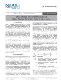
2 Cases, can obscure the Strain signals altogether. In order to Control the Noise level, and maximize the signal-to- Noise Electrostatic fields are generated by the presence of ratio, it is necessary first to understand the types and voltage with, or without current f low. Alternating characteristics of electrical Noise , as well as the sources of electrical fields inject Noise into Strain gage systems such Noise . With this understanding, it is then possible to through the phenomenon of capacitive coupling, by which apply the most effective Noise -reduction measures to any charges of correspondingly alternating sign are developed particular instrumentation problem. on any electrical conductors subjected to the field (Figure 1). Fluorescent lighting is one of the more common This technical note identifies some of the more common sources of electrostatic Noise .
3 Noise sources, and describes the routes by which the Noise is induced into Strain gage circuits. It should be noted that the treatment here is limited to Noise from external electrical and magnetic sources. This note does not cover effects from nu clear or thermal sources, nor does it consider the effects of variable wiring or contact resistance caused by slip rings, connectors, switches, etc. Following the discussion of Noise sources, specific methods are given, varying with the Noise -coupling mechanism, for Noise avoidance. The information in this technical note is equally applicable to both analog and digital systems employing dc amplifiers. It also applies to systems using carrier excitation and carrier amplifiers. Noise Sources and Pickup Media Virtually every electrical device that generates, consumes, Figure 1.
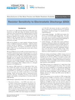
4 Electrostatic Noise coupling. or transmits power is a potential source for causing Noise in Strain gage circuits. And, in general, the higher the voltage or current level, and the closer the Strain gage circuit to Magnetic fields are ordinarily created either by the the electrical device, the greater will be the induced Noise . flow of electric current or by the presence of permanent Following is a list of common electrical Noise sources: magnetism. Motors and transformers are examples of the former, and the earth's magnetic field is an instance of the ac power lines arc welders latter. In order for Noise voltage (emf) to be developed TECH NOTE. motors and motor starters vibrators in a conductor, magnetic lines of f lux must be cut.
5 By the conductor. Electric generators function on this transformers fluorescent lamps basic principle. In the presence of an alternating field, relays radio transmitters such as that surrounding a 50/60-Hz power line, voltage will be induced into any stationary conductor as the generators electrical storms magnetic field expands and collapses (Figure 2). Similarly, rotating and soldering irons a conductor moving through the earth's magnetic field has reciprocating machinery a Noise voltage generated in it as it cuts the lines of flux. Document Number: 11051 For technical support, contact Revision: 09-Jul-2013 1. TN-501-2. Micro- Measurements Noise Control in Strain gage Measurements b) Check for line- ( mains- ) radiated Noise .
6 C) If feasible, reduce amplifier gain and compensate by increasing bridge voltage. 3. Having eliminated or satisfactorily minimized Noise pickup by the instrument, turn next to the external circuitry. With the excitation set to off, connect the gage or transducer circuit (including leadwires) to the instrument, and observe Noise . Of course, any additional Noise picked up in this step is attributed to leadwire and/or gage pickup. If the output changes when the instrument chassis is touched with a finger, this is an indication of a poor ground and/or radio- frequency interference. Figure 2. Electromagnetic Noise coupling. 4. Apply a load to the part under test (with excitation still Since most irons and steels are ferro-magnetic, moving off).
7 If additional Noise is observed, the Noise is due to machine members redirect existing lines of flux, and may something associated with the loading system such as cause them to be cut by adjacent sensitive conductors. As a motor creating a magnetic field, or the motion of the a result, signal conductors in the vicinity of moving or gage or wiring (generating emf). rotating machinery are generally subject to Noise voltages 5. If possible, remove the load from the test part and apply from this source. excitation voltage to the bridge circuit. After balancing the bridge, any subsequent change in output, if gradual, Detecting and Troubleshooting is zero-shift, not Noise . This may be due to gage self- heating effects (see Tech Note TN-502, Strain gage In order to effectively assess the presence and magnitude Excitation Levels) or other time-dependent resistance of Noise , the Strain gage instr ument selected for changes.
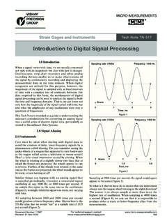
8 Use should incorporate a simple, but very significant feature provision for removing the excitation from the The following sections of this Tech Note give recommended Wheatstone bridge. With such a Control , the instrument Noise -reduction procedures for electrostatic Noise , and for output can be easily checked for Noise , independently of magnetic Noise . any Strain signal. This represents a very powerful tool for evaluating the effectiveness of shields and grounding, and Electrostatic Noise Reduction for experimentally modifying these methods to minimize the effects of Noise . All Micro- Measurements Strain gage The simplest and most effective barrier against electrostatic instruments and data systems are equipped with this Noise pickup is a conductive shield, sometimes referred to important feature.
9 As a Faraday cage. It functions by capturing the charges that would otherwise reach the signal wiring. Once collected, The following procedure can be used to troubleshoot a these charges must be drained off to a satisfactory system for Noise : ground (or reference potential). If not provided with a 1. If not already known, determine the tolerable levels of low-resistance drainage path, the charges can be coupled Noise in output units (millivolts, inches of deflection, into the signal conductors through the shield-to-cable etc.) as observed on a readout such as an oscilloscope or capacitance (Figure 3). data system display. 2. Consideration should be given first to Noise sources affecting the measurement system, isolated from all external circuits.
10 For this purpose, disconnect any TECH NOTE. Strain gage leads, and terminate the S+/S amplifier inputs with about the same input impedance that the amplifier normally senses (typically between 120 and 1000 ohms). If excessive Noise exists: a) Check for ground loops (more than one connection of the system to ground). Figure 3. Electrostatic shielding. For technical questions, contact Document Number: 11051. 2 Revision: 09-Jul-2013. TN-501-2. Micro- Measurements Noise Control in Strain gage Measurements The two most popular types of cable shields are braided In a fully guarded amplifier system (for example, Micro- wire and conductive foil. The braided-shield construction Measurements Model 2200 System), the common-mode provides about 95 percent coverage of the cable, and is voltage of the bridge excitation supply and the signal characteristically low in resistance.