Transcription of Non Condensing Models - Takagi Tankless Water …
1 Troubleshooting Guide 1| Page Non Condensing Models On Demand Water Heater Troubleshooting Guide 110 Indoor (T KJr2 IN) 110 Outdoor (T KJr2 OS)310 Indoor (T K4 IN) 310 Outdoor (T K4 OS) 510 Indoor (T D2 IN) 510 Outdoor (T D2 OS) 9/12/11 321923 000 Water Products Company500 Tennessee Waltz Parkway Ashland City, TN 37015 Toll Free: 1 877 737 2840 Troubleshooting Guide 2| Page Table of Contents 1. 2. 3. NORMAL 4. Gas Water Power 5. Preliminary General Error 12 Verifying proper Dipswitch Draining the Cleaning the Checking for a Cross Check for Reverse Check gas supply 21 Purge the gas line of 22 Adjusting manifold Resetting the computer 23 Checking the 24 6.
2 Rod Burner & Rod Heat Flow Descaling the Troubleshooting Guide Troubleshooting Guide 3| Page 1. SPECIFICATIONS Table 1 Troubleshooting Guide 4| Page 2. INTRODUCTION This manual provides the necessary information for troubleshooting the 110 (T KJr2), 310 (T K4), 510 (T D2) Tankless Water heaters. It will be effective in helping your troubleshooting needs as long as the instructions are followed in the intended order. Here is how to use this manual: First refer to the Installation Manual as the primary source of information. Refer to it along side this manual throughout the troubleshooting process. Before troubleshooting, if you are unfamiliar with how a Tankless unit operates, read the Normal Operation section (p.)
3 5). To double check/troubleshoot a new installation, use the Proper Installation section (p. 6). When beginning troubleshooting, first go through the Preliminary Checklist (p. 7); it is designed to fix the most common and frequent problems, and provide you with background information to help narrow down the information you need. After the Preliminary Checklist, move to the Error Codes section (p. 12) if you have received an error code, or to General Problems (p. 8) if you have not received an error code. If you have any problems or questions regarding this equipment, or at any point become confused or uncomfortable with any of the procedures, consult with the technical service department or service agent. IMPORTANT Installation and service must be performed by a qualified installer (for example, a licensed plumber or gas fitter). Otherwise the warranty will be void.
4 The installer/service agent (licensed professional) is responsible for correctly installing or servicing your Water heater and for compliance with all national, state/provincial, and local codes. *For all units installed in the state of Massachusetts, it is required that the installer either be a licensed plumber or licensed gas fitter. GENERAL INSTALLATION GUIDELINES 1. Follow all local codes, or in the absence of local codes, follow the most recent edition of the National Fuel Gas Code: ANSI 54 in the USA or CAN/CSA Natural Gas, Propane Installation Code in Canada. 2. Properly ground the unit in accordance with all local codes or in the absence of local codes, with the National Electrical Codes: ANSI/NFPA 70 in the USA or CSA standard Canada Electrical Code Part 1 in Canada. 3. Carefully plan where you intend to install your Water heater.
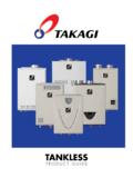
5 4. Check the rating plate for the correct GAS TYPE, GAS PRESSURE, Water PRESSURE and ELECTRIC RATING. *If this unit does not match your requirements, do not install. 5. If any problem should occur, turn off all hot Water taps and turn off the gas. Then call a trained technician or the gas company. WARNING RATING PLATE Figure 1 Troubleshooting Guide 5| Page 3. NORMAL OPERATION Becoming familiar with how a Tankless Water heater normally operates may help to figure out what is wrong with it. Assuming it is properly installed with appropriate gas, Water , and electric connections, the following is how it should operate: 1) ACTIVATION a. A hot Water tap is opened enough that the flow sensor detects a flow rate through the heater greater than the activation point of gpm. b. The fan activates after flow is detected. c. The computer checks for any problems with the unit before startup.
6 D. Igniter activates. You can hear the buzzing of the spark igniter. e. Main gas valve, proportional valve, and solenoid gas valves will open. You will hear a deep clunk clunk noise. f. Once a flame is detected, the red LED located on the computer board will activate. g. In a multi heater setup, the controller will activate the next heater in 2 4 gpm increments, depending on the set temperature. 2) OPERATION a. The proportional gas valve will modulate based on the amount of hot Water demanded and the temperature rise needed. The fan speed will modulate as well to create an efficient burn. b. You will notice that only partial sections of the burner will be lit. This is normal operation; there are three sections on the burner assembly, and the computer controls the amount of sections needed based on the flow rate and temperature rise required.
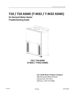
7 3) SHUTDOWN a. The heater will shut down when the Water flow rate drops below the deactivation point of gpm. b. The heater will close the main gas valve and solenoid gas valves, extinguishing the flame. c. When the flame disappears the red LED will turn off. d. The fan will increase in speed to purge the venting of any remaining exhaust gases. The length of post purge can last up to 1 minutes. e. The heater goes into standby waiting for the process to begin again. *The purpose of this diagram is to illustrate thetankless Water heater design concepts, and may not be accurate to your Models physical description. Figure 2 Troubleshooting Guide 6| Page 4. INSTALLATION 1. Follow all local codes, or in the absence of local codes, follow the most recent edition of the National Fuel Gas Code: ANSI 54 in the USA or CAN/CSA Natural Gas, Propane Installation Code in Canada.
8 2. All gas Water heaters require careful and correct installation to ensure safe and efficient operation. This manual must be followed exactly. Read the Safety Guidelines section in the installation manual. 3. The manifold gas pressure is preset at the factory. It is computer controlled and should not need adjustment. 4. Maintain proper space for servicing. Install the unit so that it can be connected or removed easily. Refer to the Clearances Section on p. 8 in the installation manual for proper clearances. 5. The Water heater must be installed in a location where the proper amount of combustible air will be available to it at all times without obstructions. 6. The electrical connection requires a means of disconnection, to terminate power to the Water heater for servicing and safety purposes. 7. Do not install the unit where the exhaust vent is pointing into any opening in a building or where the noise may disturb your neighbors.
9 Make sure the vent termination meets the required distance by local code from any doorway or opening to prevent exhaust from entering a building. 8. Particles from flour, aerosols, and other contaminants may clog the air vent or reduce the functions of the rotating fan and cause improper burning of the gas. Regularly ensure that the area around the unit is dust or debris free; regular maintenance is recommended for these types of environment. 9. If you will be installing the Water heater in a contaminated area with a high level of dust, sand, flour, aerosols or other contaminants/chemicals, they can become airborne and enter and build up within the fan and burner causing damage to the Water heater. 10. For the Indoor 110 (T KJr2 IN), 310 (T K4 IN), and 510 (T D2 IN) Models : These units may be converted to a direct vent (sealed combustion) appliance by installing a direct vent conversion kit (Part No.)
10 9007667005) which will bring in all required combustible air from outside the building. When installing the conversion kit, please follow all instructions included with the kit. If the Water heater is used as a direct vent appliance, the unit requires a 3 intake air pipe. The intake pipe must be sealed airtight. Air supply pipe can be made of ABS, PVC, galvanized steel, corrugated aluminum, corrugated stainless steel or Category III stainless steel. Terminating the venting through a sidewall is recommended for the direct vent system. Running the exhaust vent and the intake pipe parallel is recommended. Terminating the exhaust and intake on the same wall / surface is recommended. Terminating in the same pressure zone allows for pressure balancing, which prevents nuisance shutdowns. Follow venting clearance guidelines in the installation manual.