Transcription of NORTH MORECAMBE TERMINAL, BARROW AN …
1 NORTH MORECAMBE terminal , BARROWAN OVERVIEWBARRY SLOCOMBE BSc MSc MASCEENGINEERING MANAGER, KELLER RAISON BEng MSc CEng MICE MASCECHIEF ENGINEER, KELLER DAHANAYAKE BSc CEng MICE MIGasEFORMERLY PROJECT ENGINEER, BRITISH construction of the largest gas terminal in Europe was dominated by the sitebeing underlain by very poor ground conditions that were compounded by seismicconsiderations and a fast-track programme. This paper describes the civil andgeotechnical aspects of the project and gives an overview of the design andengineering decisions that were foundations successfully bid for civil and foundation works, (Civil Works 1 Contract), for the process plant at the British Gas NORTH MORECAMBE terminal sitenear BARROW in Furness. The Design and Build contract included advance civils workcomprising earthworks, drainage and road construction, soil densification using vibroreplacement techniques and piling paper describes the British Gas Project and gives background information aboutsite location, plant requirements and the site investigation.
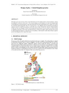
2 The paper also presentsoutline details of the unusual pile design and foundation solution proposed andinstalled by Keller to deal with poor ground conditions and overcome the earthquakerisk. Detailed descriptions of the pile design and associated seismic and earthquakeanalyses form the subject of companion papers, Raison1 and Raison et PROJECTThe NORTH MORECAMBE gas field is located in the Irish Sea about 40km south west ofBarrow in Furness, Figure 1. The field is owned by British Gas and is one of thelargest undeveloped gas fields in the UK continental shelf. Because the natural gashas a high nitrogen and carbon dioxide content, particularly large and substantialoffshore plant were required, the cost of which had precluded earlier extraction. Theproject became more economic after advances in corrosion control for the gaspipeline and development of unmanned offshore platform technologies.
3 This reducedthe required offshore facilities but at the expense of increased size of the onshoreprocessing plans for exploiting the natural gas were begun during 1987 by BritishGas Exploration and Production (BGEP). They performed design studies to considerenvironmental and other economic factors. Various locations were considered for thegas processing plant for landing the gas by pipeline and connection to the BritishGas National Transmission System. BARROW in Furness offered a suitable location onan area of derelict land adjacent to the existing South MORECAMBE Bay terminal , alsofounded on soil treated by vibro NORTH MORECAMBE terminal , in conjunction with the existing South Morecambeplant, will be capable of satisfying about 25% of the total UK gas ASSESSMENTB ecause of the critical nature of the site and its sensitive location, the BGEP designstudies included seismic hazard risk UK is characterised as being of low seismicity as it is located within the EurasianPlate in a stable continental intraplate region remote from the plate , available historical records show that the MORECAMBE Bay area has beensubject to seismic activity.
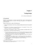
4 The assessment also highlighted the possibility thatliquefaction could occur, as had been observed on the seashore during the 1865 Rampside event, British Geological earthquake magnitudes were defined in relation to the terminal plant items were to be designed for a 1 in 10,000 year return periodequivalent to a Richter scale earthquake event with epicentre at 15km distanceand 10km depth. Non critical hazardous plant were to be designed for a 1 in 500year return period equivalent to on the Richter scale. Although a criterion fornormal structures was defined, in practice, all plant was covered either by the 1 in500 year or 1 in 10,000 year criteria. Table 1 gives a summary of assessed peakbedrock acceleration for each earthquake together with anticipated amplification ofthe response spectra through the superficial deposits giving higher peak groundsurface NORTH MORECAMBE SITEThe NORTH MORECAMBE terminal site is located to the NORTH of the existing British GasSouth MORECAMBE terminal , Figure 2, approximately 2km south-east of BARROW inFurness.
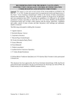
5 The site is approximately 750m long in the NORTH -south direction and about250m wide. The site is bounded by the coast to the west and undulating pastureland to the east, with a bird sanctuary and an area of Special Scientific Interestnearby. Stringent environmental restrictions were applied which dictated that thesite be developed at a level between 9mOD and development, the majority of the 20ha (50 acre) site, Figure 3, comprisedthree former settlement lagoons containing saturated pulverised fuel ash (PFA). ThePFA was a waste product that had been placed as a slurry over 30 years by pumpingfrom the adjacent coal-fired Roosecote Power Station. The NORTH and south PFAlagoons were generally at a higher level than the central lagoon with better drainageresulting in a crust of firmer PFA.
6 Within the lower central lagoon the PFA wasextremely soft with water at the ground surface. This area could not be trafficked byany form of the east, part of the site lay outside the boundary of the lagoon areas whichcorresponds to the old cliff line. The hillside is formed from natural soils and rises toover CONDITIONSAs part of the conceptual design, additional geotechnical studies were started duringthe latter part of 1990. These were carried out by Ove Arup & Partners and includeda detailed site investigation with boreholes, static cone penetration (CPT), piezocone,electrical resistivity and seismic cone soundings, together with plate tests, skiploading tests and extensive laboratory testing. Laboratory cyclic load testing of thePFA was also performed. Full details are given in the geotechnical report, Ove and CPT locations are shown in Figure site investigation revealed PFA underlain by a succession of alluvial sands,mixed glacial soils and sandstone.
7 A typical NORTH -south geological section is shownin Figure PFA extended down to a level of about 4mOD. It was usually extremely softwith typical SPT N values below 2 blows/300mm, Figure 6. Parts of the NORTH andsouth lagoons had been formed to higher levels where some degree of pozzolannicreaction had occurred within the upper layers. Here N values were generally size grading of the PFA indicated a sandy silt, often clayey. Chemical testingshowed evidence of heavy metal contamination above the EC alluvial deposits were up to 7m thick and varied between loose to mediumdense silty, occasionally gravelly and clayey sands, to weak silty clay with bands ofpeat. The sands had N values between 5 to 30 blows/300mm as illustrated inFigure glacial soils were extremely mixed in nature, strength and relative density overthe site as a whole comprising four main sub-divisions.
8 These were upper glacial till,fluvioglacial sand or sand and gravel, lacustrine glacial lake clay and a lower glacialtill. All sub-divisions were not present at any one location and the sands oftencontained thin layers of clay up to thick. The glacial sands typically had Nvalues varying between 5 and 30 blows/300mm as shown in Figure 6. Measured Nvalues for the lake clay varied with depth from about 15 to 20 blows/300mm, whilstN values in excess of 50 blows/300mm were recorded in the lower glacial bedrock of Triassic age was found in a number of the boreholes from -19mOD to below -29mOD. The solid geological map shows the Yarlside Fault lyingabout 750m east of the was perched within the PFA generally at about 7mOD to 8mOD andclose to ground level within the lowest part of the central lagoon.
9 In the naturalsoils, piezometers revealed a variation in groundwater level from south-east tonorth-west between about 4mOD and CIVILS CONTRACTF ollowing completion of the conceptual design and additional site investigation, theexecutive of British Gas gave the go ahead for the 500 million NORTH MorecambeProject in April 1991. Because of the high nitrogen and carbon dioxide content, thetreatment plant was particularly large and heavy. Much of the major plant itemswere to be fabricated off operational requirements were for the largest gas terminal in Europe to beprocessing gas by October 1995. However, this date was brought forward to October1994 due to a projected shortfall of supply capability during the 1994/95 winter. Thenew deadline dictated a very short construction programme of only 42 months, asillustrated in Figure 7.
10 This accelerated programme necessitated the letting of theCivil Works 1 Contract before final design of much of the process plant. Althoughconceptual design and tender documents were prepared by the Ralph M. ParsonsCompany Limited, the detailed design was performed by John Brown Engineering &Constructors Limited. British Gas were acutely aware that this situation would resultin many alterations to the foundation layouts based on the conceptual was to proceed on a fast-track programme while advance civils works were was also clear that the geotechnical and seismic problems of the site were Gas therefore took the unusual step of inviting several large specialistgeotechnical contractors to tender for the Civil Works 1 Contract. The conforming bidwas to be based on a conceptual scheme using driven precast and large diameterbored piles.