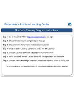
Transcription of NOTE: THIS BULLETIN SUPERSEDES TECHNICAL SERVICE BULLETIN ...
1 SUBJECT:NO:08-31-98 Rev. AFront Windshield WipersSelf-Activate While DrivingGROUP:ElectricalOr Will Not Turn OffDATE:Jul. 24, 1998 NOTE: THIS BULLETIN SUPERSEDES TECHNICAL SERVICE BULLETIN 08-31-98, DATED JUNE 26, 1998, WHICH SHOULD BE REMOVED FROMYOUR FILES. THE REVISIONS INCLUDE, REVISED SYMPTOM/CONDITIONONE, DIAGNOSIS AND REPAIR PROCEDURES FOR SYMPTOM TWO ANDTHREE, AND PARTS REQUIRED. REVISIONS ARE HIGHLIGHTED WITH**ASTERISKS**.MODELS:1996-1997(NS)To wn & Country/Caravan/Voyager1996-1997(GS)Chry sler Voyager (International Markets)SYMPTOM/ wipers will turn on while the windshield wiper switch is in the "OFF"position for one or more wipes **with the ignition ON ,** or when the turn signaland/or headlamp beam select is wipers will not turn off with the ignition switch "ON" or "OFF" and the41TE transaxle may go into limp-in mode when the windshield wipers are turned"ON".
2 Wipers stop immediately (instead of parking fully down) when the switchis turned "OFF" or continue to wipe for approximately 10 seconds after beingturned "OFF" and then stop wherever they are (instead of parking fully down) eitherby using the windshield wiper switch or the ignition :IF THE WIPE OCCURS AT VEHICLE START UP ONLY, MAKE SURE THEIGNITION OFF DRAW (IOD) FUSE IS FULLY :SYMPTOM the vehicle operator describes Symptom/Condition One, perform the RepairProcedure for Symptom Rev. A-2-SYMPTOM the ground eyelets on the engine block near the transmission dipstick should be no **1996 MODEL VEHICLES:Check the ground wire from the eyelet to CAV #5 of the gray E48 connector on thebottom of the Power Distribution Center (PDC) for MODEL VEHICLES:Check the ground wire from the eyelet to CAV #4 of the aqua C8 connector on thebottom of the Power Distribution Center (PDC) for MODEL VEHICLES.
3 Check for continuity from CAV #5 of the gray E48 connector on the bottom of thePDC to the center terminal of the windshield wiper "ON" relay (THIS IS ANEXTREMELY LOW PROBABILITY FAILURE MODE, be sure to reinstall the PDCcover properly).1997 MODEL VEHICLES:Check for continuity from CAV #4 of the aqua C8 connector on the bottom of thePDC to the center terminal of the windshield wiper "ON" relay (THIS IS ANEXTREMELY LOW PROBABILITY FAILURE MODE, be sure to reinstall the PDCcover properly).** a problem is found in steps 1 thru 3, perform the Repair Procedure for SymptomTwo.
4 -3-08-31-98 Rev. ASYMPTOM a DRB III (Scan Tool), monitor the wiper park switch input to the Body Control Module (BCM) when the windshield wipers are on. If the wiper park switchinput status does not change as the wipers are moving, the park switch circuit **1996 MODEL VEHICLES:Check for continuity between cavity #41 of the B58 BCM connector and cavity #4 ofthe wiper module B31 connector, refer to the 1996 illustration on the next page. 1997 MODEL VEHICLES:Check for continuity between cavity #41 of the C1 BCM connector and cavity #2 ofthe wiper module connector, refer to the 1997 illustration on the next MODEL VEHICLES:Check for continuity between cavity #7 of the B31 wiper module connector MODEL VEHICLES:Check for continuity between cavity #4 of the wiper module connector andground.
5 ** a problem is found in steps 1 thru 3, perform the Repair Procedure for REQUIRED:AR (1)05012382 AASwitch, Multi-functionAR (1)**04707730 PDC,1996 With 41TE TransaxleAR (1)04868131 PDC,1996 With 31TH Transaxle and Antilock Brake System(ABS)AR (1)04868132 PDC,1996 With 31TH Transaxle and Without ABSAR (1)04707892 ABPDC,1997 With 41TE TransaxleAR (1)04707893 ABPDC,1997 With 31TH Transaxle and ABSAR (1)04707891 ABPDC,1996 With 31TH Transaxle and Without ABS**AR (1)04673013 AAMotor, Wiper199608-31-98 Rev. A-4-1997-5-08-31-98 Rev.
6 A 08-31-98 Rev. A-6-REPAIR PROCEDURE:This BULLETIN involves installing a revised multi-function switch and/or ground wirecorrection and/or a PDC and/or a wiper motor the top and bottom steering column the two multi-function switch attaching screws and the multi-function switch out from the mounting housing and disconnectthe wiring the wiring harness to a new multi-function switch, p/n the new multi-function switch into the mounting housing and secure withthe two screws previously removed in step the multi-function switch has been installed properly by putting the switchlever into the left or right turn signal position and turning the steering wheel toensure cancellation the top and bottom steering column sure the ground eyelets are placed properly on the stud and the nut holdingthe eyelets and the dipstick tube is tightened there was no continuity between the ground
7 Wire eyelet wiring connector on thebottom of the PDC, locate the open in the circuit and repair there was no continuity between the PDC connector to the center terminal of thewindshield wiper "ON" relay, replace the PDC. Be sure to install the PDC there is no continuity between the BCM connector and cavity the wiper modulewiring connector as described in the Diagnosis, locate the open in the circuit andrepair Rev. there is no continuity between cavity wiper module wiring connector and groundas described in the Diagnosis, locate the open circuit and repair there is continuity as described in the Diagnosis replace the wiper motor usingthe procedure outlined in the appropriate SERVICE : Reimbursable within the provisions of the ALLOWANCE:Labor Operation No:08-80-87-93 Replace Multi-function Wiper CODE:P8 - New PartLabor Operation No:08-90-06-91 Tighten Nut For Ground CODE.
8 83 - Connection Loos