Transcription of Notes 9 Torsional Vibrations a (twisted) Overview
1 1459/659 S&V measurementsNotes 9 Torsional Vibrations a (twisted) OverviewLuis San AndresMast-Childs Chair Professor 2019 Torsional Vibrations a (twisted) Overview & Adolfo Delgado, Texas A&M University-Mechanical Engineering Department, January 2018 Contents reproduced (with permission) and adapted from Torsional Dynamic Overview course developed by Brian Murphy Rotating Machinery Analysis, Inc. Copyrighted materialME 459/659 Sound & Vibration Measurements Notes 9 The Basics of Torsional Vibrations3 Torsional vibration is oscillatory twisting of the shafts in a rotor assembly that is superimposed to the running speed. The frequency can be externallyforced, or can be an eigenvalue (natural frequency of the Torsional system ). A resonance will occur if aforcing frequency coincides with a natural frequency. Individual turbomachine rotors are usually stiff enough in torsion to avoid typical Torsional excitation frequency range.
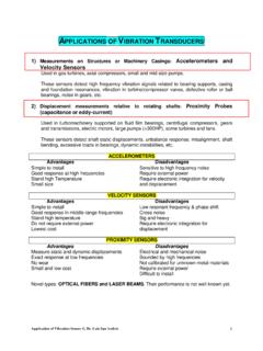
2 A typical high speed drive train includes a motor and a gearbox driving rotating machinery through flexible When rotating machines are connectedtogether via shafts or couplings, however, each of the individual rotors can act as a single massive inertia. Couplings and connecting shafts have relatively low Torsional stiffness and yield lower system natural frequencies. Torsional natural frequencies are typically low <60Hz. Synchronous electric motors can produce pulsating torque at low frequency during startup. Torsional vibration issues are more commonly associated with diesel engines (reciprocating ICEs) driving electric generators or marine Figure illustrates the 1sttorsional elastic mode (fundamental mode) The flexibility of the coupling is the dominant source of compliance. Synchronous electric motors can produce pulsating torque at low frequency during startup. A system so simple only has a single natural frequency low enough to be excited by the most typical sources of Torsional Model of a Compressor Drive TrainFrom Eshleman, Proc.
3 6thTurbomachinery Symposium, 1977 The simplest Torsional modelElastic shaftMOTOR compressor6 Coupling Failures Torsional shear cracking of shaft due tometal fatigue, usually arises in the vicinity of stress concentrations and propagate at 45oto the shaft axis Gear wear and rapiddeterioration (a few hours)of tooth surface and pittingof pitch line. May eventually result intooth fatigue. Shaft key failure and shrink fit slippage High noise level if gears become periodically unloaded Poor product surface quality, rollers insteel mills, presses, etc. Presence of 1st Torsional mode in lateral vibration signalsFatigue Fracture of a Keyed Rotating Shaft & Broken DiaphragmTorsional vibration issuesCommon Indicators7 Torsional Vibrations vs. Lateral VibrationsTorsionalLateralMeasurementReq uires special instrumentation, but in some instances is sensed through noise if gears are present. Easily detected through standard instrumentation, or through Vibrations transmitted to housings and many caseslarge amplitudesare not noticed untila coupling or amplitudesare noticed due torubbing ofinterstagesealsand turbine bladesStressesAlways results instress reversalswith potential forfatigue lateralsynchronousvibrations, thereare no stressreversals (stressis constant withcircular orbits)Natural FrequenciesIndependent ofshaft rotating byshaft rotating speed(gyroscopicsand bearings)ExcitationRarelyexperiencesinst ability (thereare exceptions).
4 There is nosynchronous (1x)torsionalexcitation, exceptfrom gear pitchline to self-excited vibration(instability)Most commonexcitation issynchronous (1X)from mustinclude all rotorsin the train, buteach rotor canoften be treatedas canusually beperformedseparately oneach body in Torsional Model 2 DOF 2 natfrequencies Since this model has no stiffness to ground,one natural frequency = zero and corresponds to unrestrained rigid body rotation of the train. Torsional system models of any level of complexity will in general have exactly one zero frequency mode corresponding to rigid body rotation of the entire most basic form of Torsional model: 2 inertias connected by a single Torsional ModelTwo inertias connected by a single natural freqs:Two inertias connected by a single freqs& mode shapesQ1Q2 DriverLoadTorsional systeemwith gears12 Turbine (high speed) drives a generator (low speed) through a gear boxIsometric view with DOFs and top view (not to scale) Torsional models with gears13 Drive trains with gears can be reduced to an equivalent system (single shaft), provided that J1and J2 >> gear gearbox amplifies the motion of the high speed shaft relative to the low speed shaft.
5 GR>1 The easiest solution is to adjust the stiffness and inertia properties of one shaft to that of an equivalent shaft running at the same speed as the other adjusted parameters can be then used with the simple expression for fnInertia 1turning at N1 Inertia 2turning at N2 Inertia 1turning at N1 Equivalent inertia turning at N1 Integrally geared compressor (IGC)PICTURES courtesy of SAMSUNG Techwin16 IGC Torsional modelIsometric view with DOFs and top view (not to scale)1616 Measurement of Torque and Angular SpeedPicture from 2019 Pump Lecture (M. Sciancaleporeet al. Sulzer17 Measurements of Torque and AngSpeedMeasurement of (drive) torque is most important in many applications as Power = Torque x Angular speed P = ToWAngular speed W is easily recorded using a tachometer (mechanical or electromechanical or electronic digital). Nowadays most tachometers are rather inexpensive and use either infra-red light or diodes to detect the passage of dark/light regions these sensors typically count pulses.)
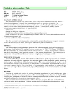
6 Other most advanced techniques include fiber optics and laser of TorqueMeasurement of steady (drive) torque is customary in dynamometers used to record the power delivered to a machine (P = ToW). This power, of course, means a cost $$ to the end user (as in $x/kWh).Many (static) torquemetersrequire the machine to be installed in (low) friction bearings or supports with the torque determined by multiplying a reaction force (F) x arm length. Figure from Doebelin, Measurement Systems, 5hth edition19A typical dynamometerPower = Torque x Angular speed P = ToW Typical configuration used to test power and efficiency of internal combustion engines (ICEs). The dyno provides a load to test the from Doebelin, Measurement Systems, 5hth edition20 Max. operating speed: 75 krpmTurbocharger driven rotorRegulated air supply: : length 55 mm, 28 mm diameter , weight= kgJournal press fitted on Shaft Stub TC cross-sectional viewTwin ball bearing turbocharger Model T25 MMFB A lab gadget for torque & lift off speedDrag Torque = Force x Arm length = (K d) x L Accelerate TC to 60 krpm and decelerate to off speed occurs at the lowest torque.
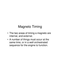
7 Airborne operation2236 N load s0204060800102030 Time [s]Rotor speed [krpm] s01002003004000102030 Time [s]Bearing torque [Nmm](a) (b) MMFB torque T0204060800102030 Time [s]Rotor speed [krpm] T01002003004000102030 Time [s]Bearing torque [Nmm](c) (d) BFB torque Rotor starts spinning Rotor stops Rotor starts spinning Rotor stops MMFB MMFB BFB BFB Time [s] Time [s] Bearing torque [Nmm] Bearing torque [Nmm] Rotor speed [krpm] Rotor speed [krpm] Static loadY WTorque and speed vs timeMetal mesh foil bearingMeasurement to determine torque and rotor lift off speed from bearings friction coefficient23 Torquemeter dynamicBased on strain deformation of a transmission shaftInstall & calibrate strain gauges. Route the signals out via slip rings.(limited to low speeds < 12 krpm) Figures from Doebelin, Measurement Systems, 5hth edition24A modern torquemeter flangeStrain gauge, no contact, low mass static and dynamic torque (to 20 krpm) wireless transmission of data (35 ksamples/s)Costly $$ Figures from Kistler25 Modeling CouplingsModeling Flexible Couplings 26 Coupling Torsional stiffness Kqas provided by coupling vendor nearly always assumes 1/3shaft penetration.
8 This means the stiffness includes everything in length F, includingthe stiffness of the shaft segment inside each hub. So attach the stiffness to each shaft at the red and damping from e-motors28 Models with Induction Motors electromagnetic stiffness and damping from induction motors. Expressions of stiffness and damping developed for reciprocating compressors but applicable to any induction motor. In turbomachinery applications, this effect is typically ignored. Situations where the emstiffness can significantly affect the 1st Torsional mode are trains using very soft elastomeric couplings(see homework)[*] 2015 Estimates Of Electromagnetic Damping Across An Induction Motor Air Gap For Use In Torsional Vibration Analysis, Ed Hauptmann, Brian Howes, Bill Eckert, Gas Machinery Conference 29EM Torsional examplePhotographs of a motor driven reciprocating compressor. [*]Feese, T., and Kokot, A., 2016, Electromagnetic Effects on theTorsional Natural Frequencies of an Induction Motor DrivenReciprocating Compressor with a Soft Coupling, Turbomachinery & 32nd Pump Symposia, Houston, TX.
9 ,September, pp. 1-22 Torsional exhibited excessive analysis at design stage omitted electromagnetic (EM) Torsional stiffness and including EM force coefficients revealed system was operating at a Torsional natural frequency30 Are Torsional systems stable?Most Torsional systems, even having a small ( Torsional ) damping are stable. However, there are important exemptionsSelf-Excited Torsional Vibration31 Positive slope of motor torque produces negative damping. Class A motors are the most efficient, but also have the longest dwell time with a positive torque-speed slope, which produces negative motor performance curveLoad vs speed32 The analogous Torsional motion equation is:where B is the slope of the linearized drive torque. The system is unstable if B> Torsional VibrationB332016 TPS, Torsional Instability of Cooling Tower Fan During Induction Motor Startup , Akira Adachi & Brian Murphy 220 kW cooling tower draft fan in a petrochemical plant.
10 Induction motor (1490 rpm) and a two stage reduction gearbox. The unit is started direct onlinewith 50 Hz power ( no VFD) 14 of 16 units experienced significant gear damage during plant commissioning. Stiffer shaft increased nat. frequency from Hz to 14 HzOriginal torqueSpeed vs timeStiffer drive shaftExampleSynchronous Electric Motor Drive Trains34 Rotordynamicsof Turbomachinery, John Wiley & Sons, 1988, pp. 55. During start up, a synchronous motor produces pulsating torque that may excite Torsional natural frequencies. API 546 covers synchronous motors over MW. A Torsional analysis is required if the motor drives a reciprocating machine. Otherwise it is up to the purchaser to specify whether or not to require a Torsional analysis, and that includes the transient startup analysis. Tasks in a Torsional Vibration Analysis35 Determine critical speeds (excite a natural frequency) and mode shapes Basic eigenvalue calculation Torsional interference diagram (Campbell diagram) Predict shaft torque response due to generic shaft orders like 1X and 2X and where the magnitude of excitation is a % of nominal torque ( % or 1%) Predict shaft torque response to transients numerical integration (time marching) Machine train start up with synchronous motors Electrical transients (starts, faults, etc.)