Transcription of Notes or rock core logging for engineering …
1 , Last saved on: 27/02/13 7:30 am GeoTek Solutions Pty Ltd Rock core logging For engineering Purposes Paul Maconochie, GeoTek Solutions Pty Ltd 1 Requirements of a Borehole Log A borehole log should provide an accurate and comprehensive record of the geological conditions encountered together with an other relevant information obtained during drilling. [1]. To which should be added that the accurate and comprehensive record should use clear terminology that is unambiguously defined. The purpose of these Notes is to help you achieve that goal. Appropriate sources for such definitions include: Australian Standard Site Investigation Code AS1726-1993[2], Rock Characterization Testing and Monitoring ISRM Suggested Methods 1981 [3] and logging of Rock Cores for engineering Purposes by the Geological Society[1]. Much of the information you will require is summarised in the AusIMM Field Geologists Manual [4] The primary borehole log may consist of a traditional paper log, a computer coding sheet or a composite paper log with imported geophysical data.
2 Some sample logs are attached at the end of these Notes . The information to be recorded can be summarized as: Basic information Project name and geographical location Borehole location as coordinates - include the geographical datum Those responsible for the borehole principal, contractor, logger Relevant dates date started drilling, date finished drilling, date of water level reading. Drilling Method and Progress Machine core barrel and bit should be described Details of core sizes and changes, use of casing, use of drilling fluids Penetration rates Groundwater observations while the hole is being drilled including standing water levels and water losses Description of Type and Condition of Material Encountered Rock type Strength Weathering Defects Structures Pictorial Log Using symbols/graphs is effective shorthand in drill core logs and helps with later correlation. Geological map symbols should conform where possible to standards published by Geoscience Australia, or more conveniently, as presented in the Field Geologists Manual [4].
3 Rock core logging for engineering Purposes 2 , Last saved on: 27/02/13 7:30 am GeoTek Solutions Pty Ltd 2 Rock Substance Description Rock Type The number of different rock types that are encountered in coal basin environments is generally small and can usually be reduced to: conglomerate, sandstone, siltstone, mudstone, claystone and coal intrusive rocks in the form of dykes or sills. Sometimes you will encounter entrenched (even if wrong) local terminology. For example, strictly mudstone consists of both clay and silt sized particles, siltstone mainly silt, claystone mainly clay. Shale is characterized by its fissility and compositionally may be a mudstone, siltstone or claystone. However usage is not always so precise. Be on the look out for tuff, often it will have the appearance of a mudstone or claystone. Colour The colour of the rock should be described in the moist condition using simple terms such as black, white, grey, red, brown, orange, yellow, green or blue.
4 Borderline colours should be described as combinations like red-brown not reddish brown . Colour intensity may be described as pale (not light), dark or mottled [2]. Grain size Grain size refers to the average dimension of the mineral or rock fragments. A classification is given in Table 1. Table 1 Particle size classification Classification mm Boulders >200 Cobbles 60-200 Coarse gravel 20-60 Medium gravel 6-20 Fine gravel 2-6 Coarse sand Medium sand Fine sand Silt, clay < Source: [2] and [3] Texture and fabric (or structure) The texture and fabric of a rock specifically refers to the arrangement of the constituent grains or crystals in a rock. It can provide an indication of how the rock formed. For example: In sedimentary rocks bedding indicates depositional conditions In igneous rocks texture indicates the rate of cooling In metamorphic rocks the foliation indicates stress conditions Rock core logging for engineering Purposes 3 , Last saved on: 27/02/13 7:30 am GeoTek Solutions Pty Ltd Table 2 lists some common structures in sedimentary rocks and in Table 3 definitions of stratification and splitting terms are given.
5 Table 2 Common structures in sedimentary rock Stratification (Planar) Stratification (Irregular) Bedding Washout Cross bedding Slump Structure Graded bedding Shale Breccia Lamination Mud Cracks Cross Lamination Source: [5] Table 3 Stratification spacing and splitting terms Bedding Term Splitting Term Thickness (mm) Extremely thickly bedded Massive >6000 Very thickly bedded Blocky 2000-6000 Thickly bedded Moderately blocky 600-2000 Medium bedded Slabby 200-600 Thinly bedded Moderately slabby 60-200 Very thinly bedded Flaggy 20-60 Laminated Moderately flaggy 6-20 Very thinly laminated Fissile <6 Source: [1] and [3]. 3 core Recovery Measurements [1] The fundamental unit of core drilling is the core run. This is the distance drilled from one removal of core from the barrel to the next. Normally a run will extend for the full length of the core barrel (usually 3 m). However, for a variety of reasons, usually because the drill bit is clogged and is not cutting the in situ rock, the driller may terminate a core run short of the full length of the barrel.
6 The materials that pass up into the core barrel may be divided into four parts: Solid core pieces 100mm or more in length, called sticks Solid core less than 100mm length, called pieces Fragments of core ( not full cylindrical sides) Additional materials that may have been lost from previous core runs including: The core stump left from the previous run. Material dropped from the core barrel during its previous withdrawal Cuttings that settled when circulation of drilling fluid was stopped; core material may also have been lost by erosion of soft, friable, or intensely fractured zones, resulting in a reduction in diameter or length of the core , or both. The eroded material may be entirely removed by the flushing system as chips. Rock core logging for engineering Purposes 4 , Last saved on: 27/02/13 7:30 am GeoTek Solutions Pty Ltd Procedure Draw a reference line along the core when it is first examined in the splits.
7 All the material in the splits is defined as the total core recovery or TCR. Material that is recovered as solid core pieces at full diameter is defined as the solid core recovery or SCR. TCR will only equal SCR if there is no fragmented material in the run. Record the TCR as a length; general practice is to ignore any fine cuttings that settled from the drilling fluid. In the final log, recoveries will be expressed as a percentage, relative to the core run length. Check with the driller for reasons for core losses. He may have noted the depth range over which the barrel dropped or where a broken zone was intersected. Alternatively, possible zones of loss may be identified later from geophysical logs. You should note any significant reduction in core diameter. Stub material may be recovered in the next run and if you are examining multiple runs of core then you can make the correction at this stage. However purists will argue that you should record stub material as a loss in the first run and if it is recovered in the next run it should be included in the length of core recovered in the second run.
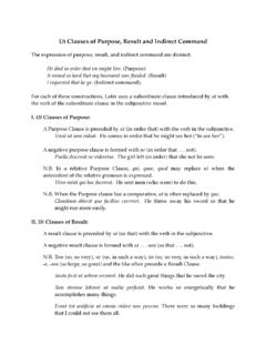
8 If you cannot identify the likely depth of core loss you should record the loss as occurring at the end of the run. 4 Rock Quality Designation (RQD) RQD was introduced by Deere [5] as a way of correlating natural fracturing intensity with engineering performance of a rock mass. RQD measurements are based on the core run. LengthRun long 100mmsticks core oflength RQD =% However, the ISRM [3] suggest that RQD values are determined for variable rather than fixed lengths of core run. Values of individual beds, structural domains, weakness zones etc. should therefore be logged separately, so as to indicate any inherent variability, and provide a more accurate picture of the location and width of zones with low or zero RQD values. Material that is obviously weaker than the surrounding rock such as over consolidated gouge is discounted, even if it appears as intact pieces that are 10 cm or more in length. The length of individual core pieces should be assessed along the centre line of the core , so that discontinuities that happen to parallel the drill hole will not unduly penalize the RQD values of an otherwise massive rock.
9 ([3], p47). An example of the calculation of RQD is shown in Figure 1. Rock core logging for engineering Purposes 5 , Last saved on: 27/02/13 7:30 am GeoTek Solutions Pty Ltd Figure 1 Example of how to calculate RQD Deere [5] also introduced a description of rock quality based on RQD. This classification shown in Table 4 was a simple classification introduced when none other existed and if used carefully can still be found useful. Table 4 Deere's classification of rock quality RQD (%) Description of Rock Quality 0-25 Very Poor 25-50 Poor 50-75 Fair 75-90 Good 90-100 Excellent 5 Fracture Frequency An alternative and complementary measure of rock quality is fracture frequency. For this, count and record the number of fractures for each metre interval of core and record the value as a number or graph of fractures per metre. Rock core logging for engineering Purposes 6 , Last saved on: 27/02/13 7:30 am GeoTek Solutions Pty Ltd RQD and fracture frequency values may be complemented by the descriptors given in Table 5.
10 Table 5 Classification of core breakage Classification Description Solid core One stick Solid core sticks Most sticks >200mm long Broken core Most pieces 60mm 200mm long Very broken core Most pieces 20mm 60mm long Fragmented core Most pieces <20mm long Disced core core broken into short flat discs 6 Rock Strength Classification The simplest and most meaningful index of strength is Uniaxial Compressive Strength (UCS). This is determined in a laboratory. Great care must be taken to ensure that samples remain at field moisture content before being tested. Samples should be taken within 5 minutes of core being recovered, enclosed with moisture proof wrapping, and stored carefully before being tested in a timely manner. If this level of care is not taken then the samples will dry out and give test results that indicate strengths much higher than they really are. Another alternative testing technique measures Point Load Strength.