Transcription of nSIGHT - Trailer Wiring Solutions, Brake Controllers, …
1 INSTALLATION PRECAUTIONS Braking capacity is for 2, 4, 6 or 8 Trailer Brake applications. This Brake control will apply the Trailer brakes while in reverse. This Brake control is inertia activated. When the vehicle is not moving, the Brake control will not automatically apply the Trailer brakes. In this event, the manual Brake must be depressed to actuate the brakes. This Brake control is not reverse polarity protected. Reversing the connection to the vehicle battery or the breakaway battery on the Trailer will damage the Brake control. This Brake control is designed to operate trailers with electric or electric/hydraulic brakes. For best results when installing components with double sided tape, make sure to prep the area by cleaning it with rubbing alcohol GUIDE Smart-Box Mounting: Locate an area under the vehicle dash on center console or kick panel to mount the Smart-Box, making sure it is not in a position that interferes with the emergency Brake or pedal operation.
2 Orientation of the Smart-Box Mount should be where [SIDE A] of the Smart-Box mounts against the kick panel or center console. Allow enough room to plug in the Brake control harness and peripheral devices easily. Mount with foam tape, cable ties or self-tapping screws (provided). Flex-Control and Flex-Display Mounting:1. Sit in the driver s seat and decide where you want to install the Flex-Display and Flex-Control . Make sure that the Flex-Display is within sight lines that will allow you to locate it easily while driving. The Flex-Control should be mounted in a position that it is within easy reach while Once the installation locations are determined, bring the Flex-Display to the area it will be mounted and begin to run the wire either behind vehicle panels or behind weather stripping down to the Smart-Box.
3 Use double sided tape to secure the Flex-Display to desired mounting location. Apply tape to the bottom of the display bracket, or remove the display bracket and attach the tape directly to the back of the display. 3. With the Flex-Control in the desired location, run the wire to the Smart-Box using the vehicle s dash seams and panels to conceal the wire. Use double-sided tape to secure the Flex-Control to desired mounting location. [Optional: Use Control Bracket and attach to dash with screws or double sided tape. Optional mounting bracket flexes to allow easy mounting to curved surfaces.] 4. With all wires routed down to the Smart-Box location, plug all peripheral wires into the Smart-Box . HOW TO ATTACH TO VEHICLE FACTORY TOW PACKAGE If your vehicle came equipped with a factory tow package, Brake control function wires may exist under the vehicle dash.
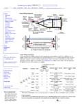
4 Consult vehicle manual or call for location. Purchase a vehicle specific Plug-in Simple! Brake control connector and simply plug into the factory tow package plug, or splice the wires to the function wires under the wire positive terminal (+) on batteryRed wire cold side of stop lamp switch or Brake lightWhite wire ground/negative terminal (-) on batteryBlue wire Trailer electric brakesVEHICLE MANUFACTURER Wiring CODES For installations on vehicles WITHOUT a factory tow package use the following procedure: 1. Be sure to use proper wire gauge when installing your control (12 gauge for electric brakes and positive power, 16 gauge for the stop lamp switch and ground).2. Connect the white wire directly to the negative post on the vehicle battery.
5 Grounding to any other location may cause intermittent Brake control operation or Attach 20-amp circuit breaker (for 6 or 8 Brake use 30-amp) or in-line fuse to the positive terminal on the vehicle s battery. Route black wire from the Brake control to the fuse or Splice the red wire into the cold side of the vehicle s stop lamp switch located by the Brake pedal. Find the wire by using a circuit tester and probing for the wire that powers the vehicle stop lamps when the Brake pedal is Route the blue wire from the Brake control to the vehicle side towing connector at the rear of the tow Some late model Ford/Mercury trucks and sport utility vehicles have 2 or more stop lamp switch wires. For proper operation, use the light green wire. The other wire is red with a green stripe.
6 This wire goes directly to ground when not in use. Splicing into this wire will short circuit your Brake control and possibly damage the unit. For Chevrolet vehicles 1999-06, if your vehicle does not have a towing package, only the ground and stop lamp switch will be active in the function wires under the dash. The electric Brake wire and 12-volt power lead will be terminated outside the firewall. These will have to be routed to the Trailer connector and battery on the vehicle. For Chevrolet vehicles 2007 New Body Style-13, only the ground and stop lamp switch will be active in the function wires under the dash. The electric Brake wire and 12-volt power lead will be terminated outside the firewall. These will have to be routed to the fuse block on the vehicle.
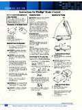
7 20-amp fuses will need to be installed to power these functions. For Dodge 2005-06, to find the cold side of the stop lamp switch, you must have the key in the on position. Ford and Dodge tow packages come with a 20-amp battery feed wire system that will accommodate 2 and 4 Brake Trailer magnets. An upgrade to a 30-amp (12 gauge) battery wire system will be needed for 6 Brake AND SETTINGYOUR CONTROLLER 1. RED DOT A red dot on bottom-right hand corner of the digital display indicates Trailer is connected. 2. BLANK A blank display (no dot) indicates Trailer is not connected. 3. POWER Power adjustment buttons (+/-) on top of the control adjust power sent to the Trailer brakes. Pressing the (-) button decreases power. Pressing (+) increases power.
8 Power will be displayed as a percentage on the digital display from 5 to 99 in increments of 5%. 4. SENSITIVITY This feature makes your Trailer braking response more or less sensitive. A setting of 1 indicates least sensitive. A setting of 7 indicates most sensitive. Adjust the sensitivity by pressing the button labeled S on the side of the unit. 5. SHORT CIRCUIT SC indicates that a short circuit has occurredTESTING / ADJUSTINGTHE BRAKING RESPONSE: Connect to your Trailer and test drive on a dry open area at low speed (20 to 25 mph). Apply vehicle brakes If Trailer brakes lock-up, adjust down the power setting to just below Brake lock-up by pressing the (-) power If the braking performance from the Trailer feels as if it is pushing the tow vehicle, adjust the power setting higher by pressing the (+) power button.
9 Repeat process until smooth braking is EN LA INSTALACI N: Capacidad de frenado es para 2, 4, 6 u 8 aplicaciones del freno del remolque. El control de frenos se aplicara en el remolque mientras este en reversa. El control de frenos se active por medio de inercia. Cuando el vehiculo no este en movimiento los frenos del remolque no se activaran autom ticamente por medio del control de frenos. En este caso, los frenos manuales deberan aplicarse. El control de frenos no esta protegido contra polaridad inversa. Invirtiendo la conexi n a la bater a del vehiculo o a la bater a del remolque da ar a el control de frenos. El control de frenos esta dise ado para operar con remolques el ctricos o el ctrico/ hidr ulicos. Para mejores resultados cuando instale componentes con tape de doble cara, aseg rese primero de limpiar adecuadamente con alcohol la A DE INSTALACI N Montaje del Smart-Box : Localizar una area debajo del tablero del vehiculo cerca de la consola central para montar el Smart-Box, asegur ndose que no interfiera con los frenos de emergencia o con la operaci n del pedal.
10 La orientaci n de el Smart-Box deber ser donde [el LADO A] del Smart-Box se monte contra la consola central. Permitiendo dejar suficiente espacio para colocar el arnes del control de frenos y dispositivos perif ricos f cilmente. Utilice el tape de doble cara, clips de banda y tornillos (incluidos) para del Flex-Control y Flex-Display :1. Primero decidir donde se colocara el Flex-Display y el Flex-Control . Aseg rese de que el Flex-Display este colocado dentro de un punto f cil de visualizar mientras este manejando. El Flex-Control deber estar montado en una posici n que sea f cilmente alcanzado mientras este Una vez que determine los lugares donde colocara ambos dispositivos, colocar el Flex-Display donde se montara y coloque el cableado detras de los paneles del vehiculo justo hasta llegar al Smart-Box.