Transcription of nstallation instrctions for part - Metra Online
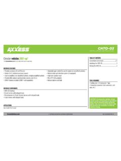
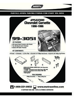
1 Metra . The World s best kits. COPYRIGHT 2004-2015 Metra ELECTRONICS CORPORATION REV. 10/12/2015 INST99-9309 Installation instructions for part 99-9309 CAUTION! Metra recommends disconnecting the negative bat-tery terminal before beginning any installation, unless the vehicle manufacturer recommends against so. Please check with your local Dealership for more information. All accessories, switches, climate controls panels, and especially air bag indicator lights must be con-nected before reconnecting the battery or cycling the ignition. Also, do not remove the factory radio with the key in the on position, or the vehicle running. It would be best to remove the key from the ignition and then wait a few seconds before removing the factory radio. ISO DIN radio provision with pocket ISO DDIN radio provision A) Radio housing B) ISO DIN brackets C) ISO DDIN brackets D) Pocket E) Climate control button covers F) Speedometer blank-out panel G) (8) #8 3/8 Phillips screwsKIT FEATURESKIT COMPONENTSWIRING & ANTENNA CONNECTIONS (sold separately)Wiring Harness: 40-EU10 Antenna Adapter: BMRC-01 Phillips Screwdriver Panel Removal Tool Socket Wrench T-20 Torx Driver T-30 Torx DriverTOOLS REQUIREDMini Cooper 2007-201599-9309 ABCDFGEDash Disassembly.
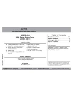
2 2-4 Kit Preparation ..5 Kit Assembly ISO DIN radio provision with pocket ..6 ISO DDIN radio provision ..7 Table of ContentsAPPLICATIONSSee inside front cover99-93092 Applications1. Open the upper glove box, and remove (2) screw covers from the left and right side. (Figure A)2. Remove (2) T-20 Torx screws from under the left side cover on the speedometer panel, and (1) from under the right side cover on the a/c vent. (Figure B)3. Unclip and remove the panel from the passenger side of the dashboard facing the door. (Figure C) Continued on the next pageDash Disassembly(Figure A)(Figure B)(Figure C)MINIC ooper (All excluding convertible) 2007-2008 Cooper (without high-def display) 2009-2012 Cooper Convertible (without high-def display) 2013-2015 Cooper Coup (without high-def display) 2013-2015 Cooper Roadster (without high-def display) 2013-201599-93094.
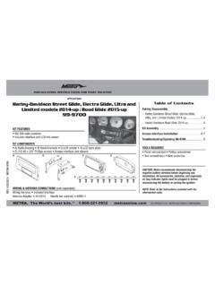
3 Remove (2) T-20 Torx screws from the passenger side a/c vent facing the door, and then unclip the vent and let it hang. (Figure D)5. Remove (2) T-30 Torx screws securing the tachometer to the steering column, and then let hang. (Figure D)6. Unclip and remove the painted panel behind the tachometer. (Figure E)7. Remove (2) T-20 Torx screws from the speedometer panel. (Figure F)8. Remove (2) screw covers inside the vent above the speedometer, and then remove (2) T-20 Torx screws uncovered. (Figure G)9. Remove the speedometer trim panel, and then disconnect the hazard switch. (Figure H)10. Remove (3) T-20 Torx screws securing the driver s knee bolster panel, and then remove. (Figure H)11. Unclip the panels from the driver and passenger side of the center stack, and then remove (2) T-20 Torx screws from each side.
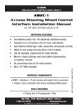
4 (Figure I)12. Unclip the trim panel from the bottom of center stack, and then remove (1) T-30 Torx screw. (Figure I) Continued on the next page(Figure E)(Figure H)(Figure F)(Figure I)(Figure D)(Figure G)Dash Disassembly399-9309(Figure K)(Figure M)(Figure L)(Figure J)13. Remove the center console. (Figure J) a. Remove (3) T-20 Torx screws from the cup holders in the center console. b. Unclip the shifter and handbrake boots. c. Remove the connectors from both the 12-volt outlet, and from the buttons that are located in front of the shifter. d. Lift the console up, and then Remove the center stack. (Figure K) a. Unplug the connectors from the climate controls, window switches, and AUX-IN jack. b. Remove (4) T-20 Torx screws securing the climate controls and window switches to the center stack, and then set aside for kit Remove (4) T-20 Torx screws from the keyhole panel, unclip, and then let hang.
5 (Figure L)16. Remove (5) T-20 Torx screws from the panel between the two glove boxes, and then unclip and remove. (Figure L)17. Remove (3) T-20 Torx screws from the speedometer, (2) from radio chassis, and then unplug and remove the assembly. (Figure M)18. Remove (4) T-20 Torx screws from the rear of the speedometer, and then remove the radio display/control panel from the cluster. Continue to kit preparationDash Disassembly499-9309(Figure A)(Figure C)(Figure B)1. Place the speedometer blank-out panel in the speedometer, and then secure using (4) T-20 Torx screws removed in step 19 of dash disassembly. (Figure A)2. For vehicles without automatic climate controls, place the climate control button covers in the radio housing. (Figure B)3. If desired, mark the trim panel removed in step 14 of dash disassembly above the bend line, and then trim off the top portion for use after the installation is completed.
6 (Figure C) Continue to kit assemblyKit Preparation599-9309(Figure A)(Figure B)(Figure C)ISO DIN radio provision with pocket1. Attach the ISO DIN brackets to the pocket using (4) #8 3/8 Phillips screws supplied. (Figure A)2. Secure the completed assembly to the radio housing using (4) #8 3/8 Phillips screws supplied. (Figure B)3. Remove the metal DIN sleeve and trim ring from the aftermarket radio. 4. Align the holes in the radio to the holes in the assembly, and then secure using the screws provided with the radio. (Figure C)5. Locate the factory wiring harness and antenna connector in the dash and complete all necessary connections to the radio and climate controls. Metra recommends using the proper mating adapter from Metra or AXXESS. Reconnect the negative battery terminal and test the radio for proper Reassemble the dash in reverse order of disassembly, using the 99-9309 radio Assembly699-9309(Figure A)(Figure B)ISO DDIN radio provision1.
7 Secure the ISO DDIN brackets to the inside edge of the radio housing using (4) 3/8 Phillips screws provided. (Figure A)2. Slide the radio into the completed assembly, and then secure using the screws supplied with the radio. (Figure B)3. Locate the factory wiring harness and antenna plug in the dash and make all necessary connections to the radio. Metra recommends using the proper mating adapters from Metra and/or AXXESS. Re-connect the negative battery terminal and test the radio for proper Reassemble the dash in reverse order of disassembly, using the 99-9309 radio Assembly7 Metra . The World s best kits. COPYRIGHT 2004-2015 Metra ELECTRONICS CORPORATIONREV. 10/12/2015 INST99-9309 KNOWLEDGE IS POWERE nhance your installation and fabrication skills by enrolling in the most recognized and respected mobile electronics school in our onto or call 800-354-6782 for more information and take steps toward a better recommends MECP certified techniciansInstallation instructions for part 99-9309 IMPORTANTIf you are having difficulties with the installation of this product, please call our Tech Support line at 1-800-253-TECH.
8 Before doing so, look over the instructions a second time, and make sure the installation was performed exactly as the instructions are stated. Please have the vehicle apart and ready to perform troubleshooting steps before The World s best kits. COPYRIGHT 2004-2015 Metra ELECTRONICS CORPORATION REV. 10/12/2015 INST99-9309 Instrucciones de instalaci n para la pieza 99-9309 PRECAUCI N! Meta recomienda desconectar la terminal negativa de la bater a antes de iniciar cualquier instalaci n, a menos que el fabricante del veh culo recomiende lo contrario. Verifique con su concesionario local si existe m s informaci n. Todos los accesorios, interruptores, paneles de controles de clima y especialmente las lu-ces del indicador de las bolsas de aire deben estar conectados antes de reconectar la bater a o ciclar la ignici n.
9 Adem s, no quite el radio de f brica con la llave en la posici n de encendido ni con el veh culo funcionando. Ser a mejor retirar la llave de la ignici n y esperar unos cuantos segundos antes de quitar el radio de f brica. Provisi n de radio ISO DIN con cavidad Provisi n de radio ISO DDIN A) Carcasa del radio B) Soportes ISO DIN C) Soportes ISO DDIN D) Cavidad E) Cubiertas de bot n de control clim tico F) Panel en blanco de salida veloc metro G) (8) Tornillos Phillips #8 de 3/8 CARACTER STICAS DEL KITCOMPONENTES DEL KITCABLEADO Y CONEXIONES DE ANTENA (se venden por separado)Arn s de cableado: 40-EU10 Adaptador de antena: BMRC-01 Destornillador Phillips Herramienta para quitar paneles llave de tubo Destornillador Torx T-20 Destornillador Torx T-30 HERRAMIENTAS REQUERIDASMini Cooper 2007-201599-9309 ABCDFGED esmontaje tablero.
10 2-4 Preparaci n del kit ..5 Ensamble del kit Provisi n de radio ISO DIN con cavidad ..6 Provisi n de radio ISO DDIN ..7 IndiceAPLICACIONESVer interior de la portada99-93092 Aplicaciones1. Abra la guantera y quite las (2) tapas de tornillos del lado izquierdo y derecho. (Figura A)2. Quite (2) tornillos Torx T-20 de debajo de la tapa del lado izquierdo del panel del veloc metro y (1) de debajo de la tapa del lado derecho de la rejilla del aire acondicionado. (Figura B)3. Desenganche y quite el panel del lado del pasajero del tablero orientado hacia la puerta. (Figura C) Continua en la siguiente paginaDesmontaje tablero(Figura A)(Figura B)(Figura C)MINIC ooper (Todo excluyendo convertible) 2007-2008 Cooper (sin pantalla de alta definici n) 2009-2012 Cooper Convertible (sin pantalla de alta definici n) 2013-2015 Cooper Coup (sin pantalla de alta definici n) 2013-2015 Cooper Roadster (sin pantalla de alta definici n) 2013-201599-93094.