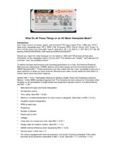
Transcription of nstallation peration and aintenance anual - Greenheck Fan
1 Document 473681 vari - green motor and ControlsVari- green motor and Controls1 Installation, Operation and Maintenance ManualPlease read and save these instructions for future reference. Read carefully before attempting to assemble, install, operate or maintain the product described. Protect yourself and others by observing all safety information. Failure to comply with these instructions will result in voiding of the product warranty and may result in personal injury and/or property of ContentsReference part number listed in chart to locate specific motor information page * RPM MethodMotor Part ..7-11 Maximum RPM Table ..123 - * Actual maximum RPM may vary . See RPM column in chart on page 11 for specific motor and fan combinations .HPVoltage* RPM MethodMotor Part motor and Controls2 Features, Operation and Wiring, and TroubleshootingFeaturesSoft start All motors feature soft-start technology which eliminates inrush current at start-up.
2 The motors will reliably start at any speed setting .Overload protection If the motor becomes overloaded, it will automatically reduce its speed until it is no longer overloaded . This means that the motor will never operate in the service factor which is possible with many AC motors .Locked rotor protection If the motor ever encounters a locked-rotor scenario, the motor will automatically shut itself down . It will try to restart up to 3 times, and if after the 3rd time the motor will still not rotate, the motor will not attempt to start again until power is cycled .Thermal protection The motors have a one-shot fuse thermal protector . This is meant to protect the motor from a severe temperature rise . Additionally, the motors have on-board temperature sensors which will reduce the speed of the motor should it become too hot.
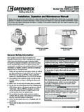
3 The fuse is used as a last resort to prevent a fire . RPM measurement The motors have a small shaft extension on the end of the motor to measure motor RPM with either a contact or optical tachometer .100 ft. or Point = Rating: 10A @ 24-240 VAC 5A @ 30 VDCA uxiliaryContactTO REMOTE DEVICEPROVIDED BYOTHERSLow voltage, route away from high voltage lines and/or use shielded cableFactory WiringField Wiring115/230 VAC input to match motor name plateGreen indiator light Power present2 x 4 Junction BoxTransformer AssemblyFig . 1 0-10 VDC External connection with factory mounted transformer (See page 4 for details) vari - green MotorThe vari - green motor is an electronically commutated (EC) motor that uses AC input power and internally converts it to a DC power supply which provides an 80% turndown capability and increased energy savings.
4 NOTEWhen using a clamp meter to measure input amp draw, the meter must be capable of reading a non-linear current . Erroneous readings will occur otherwise .WARNINGTo reduce the risk of fire or electric shock, do not use this motor with any solid-state speed control device . vari - green motor and Controls3 Part Numbers Covered in this Section309025309026310107310306310307311 352 These motors will accept a 0-10 VDC control signal for speed control . From 0-1 .9V, the motor will be off, and will operate in the 2-10V range . 24 VAC/DC power is also required for operation . The motor will consume 0 .7VA at 24 VAC or 25mA at 24 VDC . A factory mounted transformer is available to supply this voltage . (See Fig . 1)The motor is pre-wired at the factory and cannot be changed inside the motor . Connect single-phase power at the voltage listed on the nameplate, along with the 0-10 VDC and 24V signal for speed control.
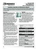
5 NOTE: The motor will not operate without the proper control voltages .Operation and Wiring - 0-10V Input OnlyOperation and Wiring - Potentiometer Dial OnlyThese motors feature a potentiometer dial on the motor for speed adjustment . A small screwdriver can be used to make the speed adjustment . To increase the speed, rotate the dial clockwise . To decrease the speed, rotate the dial counterclockwise .The motor is pre-wired at the factory and cannot be changed inside the motor . Connect single-phase power at the voltage listed on the nameplate .These motors cannot be converted to receive a remote control signal a different motor is needed . Please consult the factory .Part Numbers Covered in this Section309028309029310108310475310476311 353 Part Numbers Covered in this Section310359311731311377311388311812312 3593123603123613123623126193132333132343 1323531371231371331371431371531453431494 5316495316496316497316498316499317706317 707317708317709 Operation and Wiring - Potentiometer Dial and 0-10V InputThese motors have both a potentiometer dial on the motor for speed adjustment AND have the ability to accept a 0-10 VDC signal for remote speed control.
6 There is a 4 second delay between the application of power and the motor starting .The motor is pre-wired at the factory and cannot be changed inside the motor . Connect single-phase power at the voltage listed on the nameplate . If remote control is desired, connect the 0-10 VDC and 24V signal for remote speed control .Dial on motor A small screwdriver can be used to make the speed adjustment . To increase the speed, rotate the dial clockwise . To decrease the speed, rotate the dial counterclockwise . There is no need to connect the control wires .0-10 VDC signal The dial on the motor must be rotated fully clockwise to achieve the full speed range . If this is not done, the dial will act as a maximum speed limiter .From 0-1 .9V, the motor will be off, and will operate in the 2-10V range . 24 VAC/DC power is also required for operation.
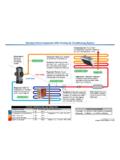
7 The motor will consume 0 .7VA at 24 VAC or 25mA at 24 VDC . A factory mounted transformer is available to supply this voltage . (See Fig . 1, page 2)A low voltage wiring harness is needed to supply the 0-10V signal to the motor . This harness is available from the factory if conversion is necessary .Low Voltage Harness Part NumbersTypeUse with Motor18 in. long36 in. long3-pin311731, 3103593844313844329-pin312359, 311377, 311812, 311388, 312360, 312361, 312362, 312619, 313233, 313234, 313235, 313712, 313713, 313714, 313715, 314534, 314945, 316495, 316496, 316497, 316498, 316499, 317706, 317707, 317708, 317709 3848043848050-10V Analog input connectionRed+ 0-10 VDCW hiteCommon*Black+24 VAC/DC * Common is shared between both 24V power and 0-10V signal .The impedance of 0-10V circuit is 12K NOTEThe 9-pin connector on the motor contains 6 wires.
8 The red, black and white wires are used for the external control signal and the other three are used for factory initialization and programing . vari - green motor and Controls4 Part Numbers Covered in this Section318003318004318013319356319357320 587320588320589320590 These motors have the ability to accept a plug in potentiometer for speed adjustment AND the ability to accept a 0-10V signal for remote control .There is a 4 second delay between the application of power and the motor starting . motor part numbers 318003, 318004 The motor is prewired at the factory and cannot be changed inside the motor . Connect single-phase power at the voltage listed on the nameplate . motor part numbers 318013, 319356, 319357, 320587, 320588, 320589 and 320590 The motor is prewired at the factory and can operate on 115v up to 277v . Operating voltage is changed via voltage jumper wire.
9 Voltage jumper For 115v the red jumper wire on the side of the motor must be connected (closed) . For 208v-277v operation the red jumper must be disconnected (open) .Dial on motor A potentiometer (p/n 385806) can be plugged into the 9-pin connector of the motor . To increase speed, rotate the dial clockwise . To decrease speed, rotate the dial counterclockwise .0-10 VDC Signal From 0-1 .9V, the motor will be off, and will operate in the 2-10V range . A low voltage wiring harness is needed to supply the 0-10V signal to the motor . The harness is available from the factory if conversion is necessary .Operation and Wiring - Potentiometer and 0-10V InputLow Voltage Harness Part NumbersTypeUse with Motor18 in . long36 in . long9-pin318003, 318004, 318013, 319356, 319357, 320587, 320588, 320589, 320590385821385822 NOTEThe 9-pin connector on the motor contains 6 wires.
10 The yellow, orange, red and white wires are used for external control . The other two wires are used for factory initialization and programming .0-10V Analog Input ConnectionRed+ 0-10 VDCW hiteCommonFactory Mounted Transformer (Fig . 1, page 2)A factory mounted transformer is available to supply 24 VDC power to the motor when the 0-10V signal is by others . This transformer has the capability to power a remote device if desired . The power available to a remote device is 400mA at 24 VDC . If the remote device is powered by a different source, connect the analog output to the 0-10V and COM terminals of the transformer . This will pass the signal through to the motor .WARNINGDo not connect an external 24V supply to the transformer's control terminal labeled 24V . If the external device providing the 0-10V signal is powered elsewhere, this terminal can remain unused.