Transcription of NTE1290 Integrated Circuit AM Tuner for Car Radio
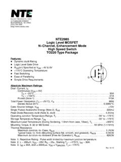
1 NTE1290 Integrated CircuitAM Tuner for Car RadioFeatures:DComplete 1 chip AM TunerDGood High Input Characteristics Provided with Automatic Dynamic Range Mag. Control at RFState (THD = 1% Typ. at 130dB )DHigh AGC FOM (63dB Typ)DGood Usable Sensitivity (23dB Typ.)DLow Distortion ( Typ. at 74dB )DGood Beat Characteristics (3fi beat = 40dB at 108dB Input, at fi = )DLarge Two Signal Selectivity (55dB Typ. at Desired 54dB )DCut Off Pop Noise at DetuningDStandard Power Supply Voltage Area is through ( typ) and Local OscillationStopping Voltage is Less Than Maximum Ratings: (TA = +25 C unless otherwise specified)Supply Voltage, VCC16V.
2 Power Dissipation (TA = +60 C), PT550mW.. Operating Temperature Range, Topr 30 to +70 C.. Storage Temperature Range, Tstg 55 to +125 C.. Electrical Characteristics:(TA = +25 C, VCC = , fc = 1000kHz, fm = 400Hz, Output Powerof Power Stage , RL = 4 unless otherwise specified)ParameterSymbolTest ConditionsMinTypMaxUnitCurrent DrainICCVCC = at zero signal 15 mASignal to Noise RatioS/NInput = 34dB , 30% dBAGC FOMO utput Base at 74dB input, Test at the10dB output down, 30% dBTotal Harmonic DistortionTHDI nput = 11dB , 30% MOD. at S/N = 20dB, 30% MOD. 23 dB VCC1st IF Amp InputVCC2nd IF Amp Input1st Amp OutputPin Connection DiagramRF Amp OutputGNDC onverter OutputLow InputConverter InputDetector OutputAGC BypassAGC BypassRF BypassRF Amp ( ) ( ) ( ) ( ) ( ).
3 700 ( ).100 ( )