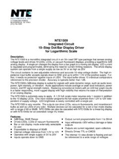
Transcription of NTE955M NTE955S NTE955SM Integrated Circuit …
1 NTE955 MNTE955 SNTE955 SMIntegrated CircuitTiming CircuitDescription:The NTE955 series timing Circuit is a highly stable controller capable of producing accurate time de-lays, or oscillation. Additional terminals are provided for triggering or resetting if desired. In time delaymode of operation, the time is precisely controlled by one external resistor and capacitor. For astableoperation as an oscillator, the free running frequency and the duty cycle are both accurately controlledwith two external resistors and one capacitor. The Circuit may be triggered and reset on falling wave-forms, and the output structure can source or sink up to 200mA or drive TTL :DDirect Replacement for 555 TimersDTiming from Microseconds through HoursDOperates in Both Astable and Monostable ModesDAdjustable Duty CycleDHigh Current Output Can Source or Sink 200mADOutput and Supply TTL Compatible TTLDT emperature Stability of per CDNormally ON or Normally OFF OutputDAvailable in Three Types: NTE955M 8 Lead DIPNTE955S 8 Lead SIPNTE955SM SOIC 8 (Surface Mount)Applications:DPrecision TimingDPulse GenerationDSequential TimingDTime Delay GenerationDPulse Width ModulationDPulse Position ModulationDLinear Ramp GeneratorAbsolute Maximum Ratings: (TA = +25 C unless otherwise specified)Power Supply Voltage.
2 VCC18V.. Discharge Current (Pin7), I7200mA.. Power Dissipation, PD625mW.. Derate Above 25 C5mW/ C.. Operating Temperature Range, TA0 to +70 C.. Storage Temperature Range, Tstg 65 to +150 C.. Lead Temperature (During Soldering, 10sec), TL+260 C.. Electrical Characteristics: (TA = +25 C, VCC = 5V to 15V unless otherwise specified)ParameterSymbolTest ConditionsMinTypMaxUnitOperating Supply Voltage 16 VSupply CurrentICCRL = ,VCC = 5V State,Note 2 VCC = 15V 1015mATiming ErrorInitial Accuracy C = FR = 1k to 100k , Note 3 %Drift with Temperature 50 ppm/ CDrift with Supply Voltage %/VThreshold VoltageVTH x VCCT rigger VoltageVTVCC = 5V VVCC = 15V VReset CurrentIR mAThreshold CurrentITHNote 4 ADischarge Leakage Current (Pin7)Idis 100nAControl Voltage LevelVCLVCC = = Voltage LowVOLVCC = 5 VISINK = 5mA = 15 VISINK = 10mA = 50mA = 100mA = 200mA VOutput Voltage HighVOHVCC = VVCC = 15 VISOURCE = VISOURCE = 200mA VRise Time of OutputtOLH 100 nsFall Time of OutputtOHL 100 nsNote 2.
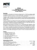
3 Supply current when output is high is typically 1mA 3. Tested at VCC = 5V and VCC = 15V. Monostable 4. This will determine the maximum value of RA = RB for 15V operation. The maximum totalR = 20M .Pin Connection DiagramNTE955M, NTE955 SMNTE955S(Front View)VCCR esetDischargeThresholdTrigger1234 GNDO utput8765 Control VoltageVCCC ontrol ( ) ( ) ( ).100 ( ) ( ) ( ) ( ).390 ( ) ( ).145 ( ).300( ).300 ( ).100 ( ).198 ( ).236( )NOTE: Pin1 on Beveled ( )061( ).006 (.152) ( ).050 ( )016(.406)