Transcription of Numerical and Experimental Investigations of Lift and Drag ...
1 Abstract In the present work, we studied Numerical and experimentally analysis lift and drag performances of NACA 0015 airfoil at different attack angle at low Reynolds numbers (Re) by measuring the forces every two degrees from 0 to 20 . The experiment test was conducted in low speed wind tunnel, and the Numerical analysis was performed using CFD program which was FLUENT. The results obtained from experiment and Numerical were compared. In this study, stall angle depended on turbulent occurred behind airfoil was determined. As result, effect of the stall angle of airfoil performance was investigated. Index Terms Angle of attack, CFD, NACA 0015, wind tunnel. I. INTRODUCTION Energy is very important for human life. As it is well-known, energy is produced by fossil fuels, but fossil fuels have two problems.
2 First, its resources are very limited. Second, they lead to environmental pollution. For this reason, renewable energy as alternative resource is emerged necessarily. One of the renewable energy is wind energy. Wind turbines use wind energy to transform into electrical energy but wind turbines efficiency is not good. Because of that, a number of scientists are investigated over wind turbines and wind turbines parameters. One of the most important parameter of wind turbines is wing because wind hits to the wings and energy of wind is transformed into the mechanical energy by wings. In the literature, wings profiles are called as airfoils. Airfoil profile is the important parameter for wing design because wing efficiency increases depending on airfoil profile, so there are a lot of studies over the airfoil profile as Numerical and Experimental in the literature.
3 Experimental Investigations are very important due to accuracy. However, those take much time and economic and whenever we want to change a parameter about our study, it is very difficult because of time and economic. Fortunately, investigators can study very fast and easily thanks to computational fluid dynamics (CFD) programs. These programs can give as correct results as Experimental methods. Also, CFD programs can be contributed as regards time and faster according to Experimental methods. NACA airfoil types were investigated in the literature. Generally, a lot of investigators studied lift and drag performances of NACA airfoil. Bhat et al., studied oscillating of NACA 0012 airfoils at around stall angle at low Reynolds number [1]. Benard et al., have investigated on the Manuscript received March 20, 2014; revised August 1, 2014.
4 Zzet ahin is with Gazi University, Faculty of Technology, Department of Energy Systems Engineering, 06500 Teknikokullar/Ankara, Turkey (e-mail: enhancement of the air foil performance by using a plasma actuator in steady and unsteady models [2]. Yao et al., have computed aerodynamic performance analysis of NACA0018 wind turbine airfoil by using Numerical simulation method. The authors investigated lift, drag performances and surface pressure by changing attack angle using different turbulence model [3]. Lianbing et al. have investigated performance of wind turbine NACA0012 airfoil using FLUENT programs. Spalart Allmaras turbulence model to Numerical solutions was used by Lianbing et al. of airfoil at 3 106 Reynolds number for lift and drag performance and stall angle [4]. Villalpando et al. studied over NACA 63-415 airfoil profile.)
5 They used different turbulence model in FLUENT and they saw that SA (Spalart Allmaras) model was better than others models. Also, they investigated aerodynamics of airfoil at low and high angles of attack [5]. Ravi et al. studied over NACA4412 airfoil profile at 3 106 Reynolds numbers. The authors investigated transition from laminar flow to turbulence flow by using two different Numerical models which were k-epsilon and Spalart Allmaras. Numerical results were compared with Experimental results. They indicated two Numerical models gave similar results at high Reynolds number [6]. Troolin et al., investigated Gurney flap effect on NACA 0015 airfoil. Initially Daniel Gurney used this flap design on race car so this flap structure known Gurney flap [7]. Troolin et al., added Gurney flap with NACA 0015 airfoil and they numerically investigated performance of this new design.
6 They saw that lift coefficient increased but drag coefficient was not change so this design was useful [7]. Siauw et al., studied on transient dynamics of the flow around the NACA 0015 airfoil by using fluid vortex generator. They experimentally investigated flow separation on NACA 0015 airfoil at 1 106 Reynolds number [8]. Srinivosan et al., studied on evaluation of turbulence models for unsteady flows of an oscillating airfoil. They studied on NACA 0015 airfoil by using five different turbulence model. They saw that Spalart Allmaras turbulence model had good agreement with Experimental results for lift, drag and moment coefficient [9]. In the present work, the lift and drag performances of NACA 0015 wind turbine airfoil were investigated as Numerical and experimentally. Also, different turbulence models were performed.
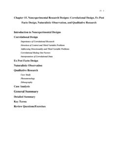
7 Obtained Numerical results were compared with Experimental results. II. Experimental SET UP The measurements have been conducted in an open wind tunnel at the University of Gazi, Faculty of Technology. This tunnel test section long is about long and flow cross- section is approximately , interval of wind velocity is from to 28 m/s. Fig. 1-a and 1-c. The airfoil Numerical and Experimental Investigations of Lift and Drag Performances of NACA 0015 Wind Turbine Airfoil zzet ahin and Adem Acir International Journal of Materials, Mechanics and Manufacturing, Vol. 3, No. 1, February 201522 DOI: used in the present study is an academic NACA 0015 profile as shown in Fig. 1-b. (chord length, c, of 100 mm and spanwise length, s, of 100 mm). Stationary end plates are kept on the two sides of the airfoil, with a small gap of about 1 mm, to help maintain two dimensionality of the flow.
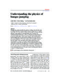
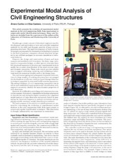
8 The experiments has been conducted at 10 m/s wind velocity (V) in tunnel which is corresponding to 68490 Reynolds number (Re). Fig. 1-a. Wind tunnel test area. Fig. 1-b. Airfoil details. Fig. 1-c. Wind tunnel test mechanism. The airfoil is forced stationary wind velocity to learn lift and drag coefficient, the airfoil profile is attached to electronic two- component coefficient transducer. The values for drag and lift are displayed digitally on the measurement amplifier. (see Fig. 2) The angular position of the airfoil (angel of attack at air foil) in the flow is set by means of a graduated dial. Angle( )Cl& 18 Mar2014 |Frame001 18 Mar2014 | Fig. 2. Lift and drag coefficients at Experimental result. Fig. 3-a. Structure of C mesh using Numerical analysis Fig. 3-b. Mesh around the airfoil.
9 III. RESULTS AND DISCUSSIONS In this study, Experimental and Numerical analyses were performed. The experiments were conducted at 10 m/s wind velocity (V). Lift and drag coefficient of NACA 0015 airfoil at different attack angle between 0 and 20 were measurement. Also, the lift and drag coefficient were obtained as Numerical with FLUENT programs for the same conditions. In Numerical analysis C mesh used as shown in Fig. 3-a and Fig. 3-b. The top bottom and left boundaries were placed at a distance of 10 chords from airfoil whereas the right boundary was placed at 20 cords. A mesh independence study was performed to verify that the solution would not change subsequent additional refinements and 33600 grids number suitable for our model. Airfoils have various shape and sizes.
10 Therefore, non dimensional coefficients (lift and drag coefficients) were taken into consideration to evaluate the advantages and disadvantages of airfoils. The non dimensional coefficients for two dimensions solution were given as below: Lift coefficient: 22lLCVc (1) Drag coefficient: 22dDCVc (2) where L and D are lift and drag force respectively, Cl and Cd are lift and drag coefficient of airfoil respectively, c is airfoil cord length, V is velocity of wind, is density of air. The lift and drag coefficient at wind tunnel test for NACA 0015 airfoil were measured as experimentally. The maximum lift and drag coefficient were found as and for 16 attack angle. The lift and drag coefficient was primarily effected by attack angle as regards both increasing and decreasing.