Transcription of NUP2105L, SZNUP2105L ESD Protection Diode
1 Semiconductor Components Industries, LLC, 2003 October, 2017 Rev. 91 Publication Order Number: nup2105l /DNUP2105L, SZNUP2105 LESD Protection DiodeDual Line CAN Bus ProtectorThe SZ/ nup2105l has been designed to protect the CANtransceiver in high speed and fault tolerant networks from ESD andother harmful transient voltage events. This device providesbidirectional Protection for each data line with a single compactSOT 23 package, giving the system designer a low cost option forimproving system reliability and meeting stringent EMI 350 W Peak Power Dissipation per Line (8/20 msec Waveform) Low Reverse Leakage Current (< 100 nA) Low Capacitance High Speed CAN Data Rates IEC Compatibility: IEC 61000 4 2 (ESD): Level 4, 30 kV IEC 61000 4 4 (EFT): 40 A 5/50 ns IEC 61000 4 5 (Lighting) A (8/20 ms) ISO 7637 2 Pulse 2a: Repetitive Load Switch Disconnect, A ISO 7637 3 Pulse 3a,b: Repetitive Load Switching Fast Transients,50 A Flammability Rating UL 94 V 0 SZ Prefix for Automotive and Other Applications Requiring UniqueSite and Control Change Requirements.
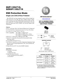
2 AEC Q101 Qualified andPPAP Capable These Devices are Pb Free, Halogen Free/BFR Free and are RoHSCompliantApplications Industrial Control Networks Smart Distribution Systems (SDS ) DeviceNet Automotive Networks Low and High Speed CAN Fault Tolerant 23 CASE 318 STYLE 27 PIN 1 PIN 3 PIN 2 MARKING DIAGRAM27E= Device CodeM= Date CodeG= Pb Free PackageSOT 23 DUAL BIDIRECTIONALVOLTAGE SUPPRESSOR350 W PEAK POWER127 EMGGCANT ransceiverCAN_HCAN_LNUP2105 LCAN BusSee detailed ordering and shipping information in the packagedimensions section on page 2 of this data INFORMATION(Note: Microdot may be in either location) nup2105l , RATINGS (TJ = 25 C, unless otherwise specified)SymbolRatingValueUnitPPKPeak Power Dissipation8/20 ms Double Exponential Waveform (Note 1)350 WTJO perating Junction Temperature Range 55 to 150 CTJS torage Temperature Range 55 to 150 CTLLead Solder Temperature (10 s)260 CESDH uman Body model (HBM)Machine Model (MM)IEC 61000 4 2 Specification (Contact)1640030kVVkVStresses exceeding those listed in the Maximum Ratings table may damage the device.
3 If any of these limits are exceeded, device functionalityshould not be assumed, damage may occur and reliability may be Non repetitive current pulse per Figure CHARACTERISTICS (TJ = 25 C, unless otherwise specified)SymbolParameterTest ConditionsMinTypMaxUnitVRWMR everse Working Voltage(Note 2)24 VVBRB reakdown VoltageIT = 1 mA (Note 3) 32 VIRR everse Leakage CurrentVRWM = 24 V VoltageIPP = 5 A (8/20 ms Waveform)(Note 4) 40 VVCC lamping VoltageIPP = 8 A (8/20 ms Waveform)(Note 4) 44 VIPPM aximum Peak Pulse Current8/20 ms Waveform (Note 4) = 0 V, f = 1 MHz (Line to GND) 30pFProduct parametric performance is indicated in the Electrical Characteristics for the listed test conditions, unless otherwise noted. Productperformance may not be indicated by the Electrical Characteristics if operated under different Surge Protection devices are normally selected according to the working peak reverse voltage (VRWM), which should be equal or greaterthan the DC or continuous peak operating voltage VBR is measured at pulse test current Pulse waveform per Figure INFORMATIOND evicePackageShipping NUP2105LT1 GSOT 23(Pb Free)3,000 / Tape & ReelSZNUP2105LT1G*SOT 23(Pb Free)3,000 / Tape & ReelNUP2105LT3 GSOT 23(Pb Free)10,000 / Tape & ReelSZNUP2105LT3G*SOT 23(Pb Free)10,000 / Tape & Reel For information on tape and reel specifications, including part orientation and tape sizes, please refer to our Tape and Reel PackagingSpecifications Brochure, BRD8011/D.
4 *SZ Prefix for Automotive and Other Applications Requiring Unique Site and Control Change Requirements; AEC Q101 Qualified and PPAPC apableNUP2105L, PERFORMANCE CURVES(TJ = 25 C unless otherwise noted)Figure 1. Pulse Waveform, IEC 61000 4 5 8/20 ms1109080706050403020100051525t, TIME (ms)% OF PEAK PULSE CURRENTWAVEFORMPARAMETERStr = 8 mstd = 20 mstd = IPP/230 Figure 2. Clamping Voltage vs Peak Pulse , CLAMPING VOLTAGE (V)IPP, PEAK PULSE CURRENT (A)303545501001020c tFigure 3. Typical Junction Capacitance vsReverse Voltage2502VR, REVERSE VOLTAGE (V)C, CAPACITANCE (pF)46810125 C201535103025 C 40 CPULSE WAVEFORM8 x 20 ms per Figure 1f = MHz, Line to Ground0510152025303540455020222426283032 34 Figure 4. VBR versus IT Characteristics 55 CTA = +150 C25 C65 CVBR, VOLTAGE (V)IT, (mA)Figure 5. IR versus Temperature Characteristics0510152025024681012IL, LEAKAGE CURRENT (nA)VR, REVERSE BIAS VOLTAGE (V)020406080100120 60 300306090120150 180 Figure 6.
5 Temperature Power Dissipation DeratingTEMPERATURE ( C)PERCENT DERATING (%)141625 C, 55 CTA = 150 C125 C65 CNUP2105L, Controller Area Network (CAN) is a serialcommunication protocol designed for providing reliablehigh speed data transmission in harsh environments. surgeprotection diodes provide a low cost solution to conductedand radiated Electromagnetic Interference (EMI) andElectrostatic Discharge (ESD) noise problems. The noiseimmunity level and reliability of CAN transceivers can beeasily increased by adding external surge Protection diodesto prevent transient voltage nup2105l provides a surge Protection solution forCAN data communication lines. The nup2105l is a dualbidirectional surge Protection device in a compactSOT 23 package. This device is based on Zener technologythat optimizes the active area of a PN junction to providerobust Protection against transient EMI surge voltage andESD.
6 The nup2105l has been tested to EMI and ESDlevels that exceed the specifications of popular high speedCAN Physical Layer RequirementsTable 1 provides a summary of the system requirementsfor a CAN transceiver. The ISO 11898 2 physical layerspecification forms the baseline for most CAN systems. Thetransceiver requirements for the Honeywell SmartDistribution Systems (SDS ) and Rockwell(Allen Bradley) DeviceNet high speed CAN networksare similar to ISO 11898 2. The SDS and DeviceNettransceiver requirements are similar to ISO 11898 2;however, they include minor modifications required in anindustrial 1. Transceiver Requirements for High Speed CAN NetworksParameterISO 11898 2 SDS Physical LayerSpecification / Max Bus Voltage(12 V System) V / 16 V11 V / 25 VSame as ISO 11898 2 Common Mode Bus VoltageCAN_L.
7 V (min) V (nom)CAN_ V (nom) V (max)Same as ISO 11898 2 Same as ISO 11898 2 Transmission Mb/s @ 40 m125 kb/s @ 500 mSame as ISO 11898 2500 kb/s @ 100 m125 kb/s @ 500 mESDNot specified, recommendedw $ kV (contact)Not specified, recommendedw $ kV (contact)Not specified, recommendedw $ kV (contact)EMI ImmunityISO 7637 3, pulses a and b IEC 61000 4 4 EFTSame as ISO 11898 2 Popular ApplicationsAutomotive, Truck, Medicaland Marine SystemsIndustrial Control SystemsIndustrial Control SystemsNUP2105L, SpecificationsThe EMI Protection level provided by the surge protectiondevice can be measured using the International Organizationfor Standardization (ISO) 7637 2 and 3 specifications thatare representative of various noise sources. The ISO 7637 2specification is used to define the susceptibility to coupledtransient noise on a 12 V power supply, while ISO 7637 3defines the noise immunity tests for data lines.
8 The ISO 7637tests also verify the robustness and reliability of a design byapplying the surge voltage for extended IEC 61000 4 X specifications can also be used toquantify the EMI immunity level of a CAN system. The IEC61000 4 and ISO 7637 tests are similar; however, the IECstandard was created as a generic test for any electronicsystem, while the ISO 7637 standard was designed forvehicular applications. The IEC61000 4 4 Electrical FastTransient (EFT) specification is similar to the ISO 7637 3pulse 3a and b tests and is a requirement of SDS CANsystems. The IEC 61000 4 5 test is used to define the powerabsorption capacity of a surge Protection device and longduration voltage transients such as lightning. Table 2provides a summary of the ISO 7637 and IEC 61000 4 Xtest specifications. Table 3 provides the nup2105l s ESDtest 2. ISO 7637 and IEC 61000 4 X Test SpecificationsTestWaveformTest SpecificationsNUP2105L ResultsSimulated Noise SourceISO 7637 212 V Power Supply Lines(Note 2)Pulse 1Vs = 0 to 100 VImax = 10 Atduration = 5000 pulsesImax = AVclamp_max = 31 Vtduration = 5000 pulsesRi = 10 W, tr = ms,td_10% = 2000 ms, t1 = s,t2 = 200 ms, t3 = 100 msDUT (Note 1) in parallel withinductive load that isdisconnected from 2aVs = 0 to +50 Vcoupled onto 14 V batteryImax = 10 Atduration = 5000 pulsesImax = AVclamp_max = 42 Vtduration = 5000 pulsesRi = 2 W, tr = ms,td_10% = 50 ms, t1 = s,t2 = 200 msDUT in series with inductor(wire harness) that isdisconnected from 7637 3 Repetitive data line fasttransients (Note 3)Pulse a Vs = 60 VImax = Atduration = 10 minutesImax = 50 A (Note 4)
9 Vclamp_max = 40 Vtduration = 60 minutesRi = 50 W, tr = ns,td_10% = 100 ns, t1 = 100 ms,t2 = 10 ms, t3 = 90 msSwitching noise of b Vs = +40 VImax = Atduration = 10 minutesIEC 61000 4 4 Data Line EFTV open circuit = kVIshort circuit = 40 A(Level 4 = Severe IndustrialEnvironment)Ri = 50 W, tr < ns,td_50% = 50 ns, tburst = 15 ms,fburst = to kHz,trepeat = 300 mstduration = 1 minute(Note 5)Switching noise of 61000 4 5 Vopen circuit = ms,Ishort circuit = 8/20 msRi = 50 WImax = ALightning, nonrepetitivepower line and loadswitching1. DUT = device under Test specifications were taken from ISO7637 2: 2004 Test specifications were taken from ISO7637 3: 1995 DUT was tested to ISO7637 2: 2004 pulse 3a,b specification for more rigorous The EFT immunity level was measured with test limits beyond the IEC 61000 4 4 test, but with the more severe test conditions ofISO 7637 , 3.
10 nup2105l ESD Test ResultsESD SpecificationTestTest LevelPass / FailHuman Body ModelContact16 kVPassIEC 61000 4 2 Contact30 kV (Note 6)PassNon contact (Air Discharge)30 kV (Note 6)Pass6. Test equipment maximum test voltage is 30 Protection Diode Protection Circuitsurge Protection diodes provide Protection to atransceiver by clamping a surge voltage to a safe level. surgeprotection diodes have high impedance below and lowimpedance above their breakdown voltage. A surgeprotection Zener Diode has its junction optimized to absorbthe high peak energy of a transient event, while a standardZener Diode is designed and specified to clamp asteady state 7 provides an example of a dual bidirectional surgeprotection Diode array that can be used for Protection withthe high speed CAN network. The bidirectional array iscreated from four identical Zener surge Protection clamping voltage of the composite device is equal to thebreakdown voltage of the Diode that is reversed biased, plusthe Diode drop of the second Diode that is forwarded 7.