Transcription of NVELOPE Installation Guide NV1. NV1
1 NV1 System 01 Issue 2017 For further information, please see: DescriptionNVELOPE rainscreen cladding brackets and framework simplify the complexity of installing facades. NVELOPE systems are designed to provide a vertical support for most fa ade types. NVELOPE s purpose-designed brackets allow for final alignment and is a back frame system (bracket and vertical L and T rail) suitable for supporting fa ade panels that require face fixing Installation Guide | Method Statement Installation Guide CLADDING HAPPEN NV1NV1 System 02 Issue 2017 NVELOPEMAKING CLADDING HAPPENR ange of Adjustment40mm adjustment markings on brackets (60 300mm). 40mm bracket has 20mm of | Method Statement Installation Guide NV1.
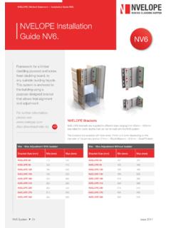
2 NVELOPE brackets are supplied in different sizes ranging from 40mm to 300mm (see table for cavity depths/cladding zones that can be formed with the NV1 system) NVELOPE also stock 60mm extension Max Adjustment With IsolatorBracket Size (mm)Min (mm)Max (mm) NVELOPE 404767 NVELOPE 6062102 NVELOPE 9092132 NVELOPE 120122162 NVELOPE 150152192 NVELOPE 180182222 NVELOPE 210212252 NVELOPE 240242282 NVELOPE 270272312 NVELOPE 300302342 Min Max Adjustment Without IsolatorBracket Size (mm)Min (mm)Max (mm) NVELOPE 404262 NVELOPE 605797 NVELOPE 9087127 NVELOPE 120117157 NVELOPE 150147187 NVELOPE 180177217 NVELOPE 210207247 NVELOPE 240237277 NVELOPE 270267307 NVELOPE 300297337NV1NV1 System 03 Issue 2017 NVELOPEMAKING CLADDING HAPPENB racketsNVELOPE brackets are available with 11mm or slots, depending on the diameter of the required primary anchor (11mm Block\Masonry and Steel/Timber).
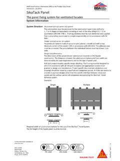
3 These are available as singles and | Method Statement Installation Guide NV1. Single Bracket Double BracketNV1NV1 System 04 Issue 2017 NVELOPEMAKING CLADDING HAPPENNVELOPEP rimary | Method Statement Installation Guide NV1. NVELOPE brackets are secured directly to a new or existing substrate of; concrete, brickwork or blockwork, steel, timber frames or SIPS. Stainless steel fixings are recommended by NVELOPE to prevent bimetallic primary anchors are designed to fix the brackets to a pre-determined grid to suit the cladding panel layout. Please liaise directly with preferred primary fixing supplier and/or panel manufacturer re pull-out. NVELOPE can assist here.
4 ImportantThe size and type of primary fixing for the brackets will always be determined by the dynamic and dead loads they have to resist. Please liaise with NVELOPE Technical Department: addition, if there is no sheathing board, the isolation of two different metals must be considered for two reasons; 1: bimetallic corrosion and 2: thermal bridging. The use of an NVELOPE isolator pad will achieve see: Fixings 1 Timber Steel Concrete/block work x 40 x L3000 = 3 metre length (also comes in 6 metre and metre) x 100 x T3000 = 3 metre length (also comes in 6 metre and metre) x 80 x T3000 = 3 metre length (also comes in 6 metre) x 100 x T3000 = 3 metre length (also comes in 6 metre and metre) x 120 x T3000 = 3 metre length (also comes in 6 metre and metre) x 140 x T3000 = 3 metre length (also comes in 6 metre) x 40 x L3000 = 3 metre length for horizontal useNV1 System 05 Issue 2017 NVELOPEMAKING CLADDING HAPPENNVELOPEV ertical | Method Statement Installation Guide NV1.
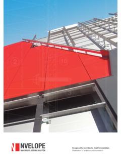
5 Vertical RailsOnce a line of vertical brackets is installed, L rail/ T rail can be attached using the helping hand at each bracket position. As the panels will follow any irregularity or miss-alignment of rails, it is important that time is taken to align and level the framework to a high standard. Each L or 'T' rail should be cut to the required length , from standard length rails (please see table above). Place the rail in each of the brackets using the helping hand to support the rail. Move the rail into its vertical position allowing 10mm expansion gaps between , profiles are cut to lengths that reflect the storey height. Typically storey-height profiles are cut so that the panel(s) are located on one set of vertical profiles and does not bridge the 10mm expansion gap between two each profile is secured to the brackets ONE, near the centre of the profile, MUST be connected with fixings going through the HOLES.
6 (Fixed point) ALL other brackets should then be fixed in the SLOTS (sliding point).For precise fixed point and sliding points speak to NVELOPE for a project specific static calculation to be System 06 Issue 2017 NVELOPEMAKING CLADDING HAPPENNVELOPEV ertical | Method Statement Installation Guide NV1. The profile can then be eased outwards to form the specified cavity depth. Check for line and level. The correct combination of single brackets/double brackets, fixed and sliding points can be determined by completing a Project Builder .Please see: Secure the rail using stainless steel screws to the fixed or sliding POINT Absorbs dead POINT Absorbs dynamic loads & note: Please note: the correct fixed and sliding points on the helping hand bracket must be used.
7 After adjustments are made for line and level, they are fixed using self-drilling stainless steel screws, SR2 ( X16).NV1NV1 System 07 NVELOPEMAKING CLADDING | Method Statement Installation Guide NV1. Once all brackets and rails are installed to an area of cladding, final checks should be carried out: On the primary anchor torque settings. To the line and level of the NVELOPE profiles in relation to each other. To the number of screws and their position in each NVELOPE insulation is specified, it should be cut and tightly butted around the brackets and secured with the appropriate fixings. Sufficient insulation fixings should be provided to ensure that the insulation cannot block the ventilated Installation (General) Check profile positions in relation to actual panel positions and joints.
8 Raise the panel and support in position. Adjust level and height of panel before fitting next panel above. Repeated on next panels. Panel joints should follow the manufactures recommendations re joint gaps horizontal and help with a smooth Installation of our rainscreen support systems there are a few things to be taken into account. Please see check list below:Has a project specific project builder been completed? you or colleagues are new to our system, have you requested a tool box talk? you referred to our data sheets and Installation guides available on our website? these tasks have been completed and Installation starts you can send our team a photo of a selection of brackets for technical to sign off or advise.
9 01707 333 396 Has a successful pull out test been completed? ChecklistNV1 NVELOPE Rainscreen Systems 10 Blenheim CourtBrownfieldsWelwyn Garden CityHertsAL7 1 ADT: 01707 333 reserve the right to change technical modifications. No responsibility is taken for detail changes or printing mistakes of the details provided.