Transcription of NVIS ANTENNA THEORY AND DESIGN - Region 6 Army …
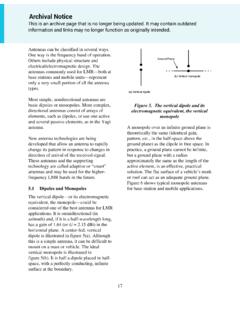
1 1 nvis ANTENNA THEORY AND DESIGN AAR6UK 20 FEB 2017 Requirements A properly designed Near Vertical Incident Skywave ( nvis ) ANTENNA will have a directivity pattern that will maximize transmission and reception at high angles while rejecting low angle, long range noise. Further, this ANTENNA must be tunable over at least an octave of frequency to track the local Critical Frequency (CF). The required directivity pattern is shown in Figure 1. Figure 1: Required nvis ANTENNA Vertical Directivity Pattern The vertical or elevation directivity pattern should have a beam width (-3dB) of approximately 100 and the horizontal or azimuth directivity pattern should be omni- directional. The three-dimensional pattern should look like a toy balloon with the filler at the bottom. Distant Noise Reduction As we have all noticed, the most prevalent noise is long-range lightning from thunderstorm activity in the surrounding states. During summer evening nets, after D- layer absorption has dropped, thunderstorms, several states away can disturb Texas Army MARS nets.
2 The south-of-the-border interference also falls into this category. There is little we can do about local thunderstorm noise, but a properly designed nvis ANTENNA can reduce the distant noise. An Australian scientist, Coleman, measured the noise directivity at both Alice Springs, Australia, and in South England ( Coleman, The Directionality Of Atmospheric Noise And Its Impact Upon An HF Receiving System, HF Radio Systems and Techniques, Conference Publication No. 473 IEE 2000). The results of this study are shown in Figures 2 and 3. The horizontal direction, or azimuth, of the noise is displayed around the circle with North being towards the top of the page. The vertical angle or elevation, is depicted as the radial distance from the center with the center of the circle being 90 or overhead. Each doted-line circle represents 30 of elevation. Ionosphere F2 Layer 200 miles 100 2 Figure 2: Vertical Angle of Arrival of Distant Noise Alice Springs Figure 3: Vertical Angle of Arrival of Distant Noise South England In both figures, the noise arrived at vertical angles of less than 30.
3 These thunderstorms, just like ours, are more likely to occur at various long ranges than on top of us. If we can achieve the directivity shown in Figure 1, we can achieve from 5dB to 15 dB of attenuation against distant noise. A more advanced nvis ANTENNA DESIGN might do even better. 3 Generating the Correct ANTENNA Pattern Optimum Height The correct ANTENNA pattern, shown in Figure 1, is surprisingly easy to generate. First let s look at the THEORY . Figure 4 shows a theoretical two-element yagi designed for 75m ( MHz). The ANTENNA consists of a half-wave dipole driven element and a passive reflector . The reflecting element is 5% longer than the driven element and is located wavelengths behind the driven element. This is a very standard 2-element Yagi DESIGN . The resulting azimuth and elevation patterns can be seen in Figures 5 and 6. ft. ~ reflector ( ft) Driven ( ft) Figure 4: Theoretical 75m Yagi 4 Figure 5: Azimuth Pattern for 2-element Yagi 5 Figure 6: Elevation Pattern for 2-element Yagi If this ANTENNA were rotated 90 with the reflector toward the ground, the pattern would begin to resemble the required nvis pattern.
4 If the reflector is replaced by real (Sommerfeld-Norton, Average) ground and the 75m dipole placed at wavelengths or 39 ft. above the ground, the elevation plot of Figure 7 results. 6 Figure 7: Elevation Pattern For a nvis 75m Dipole The azimuth plot is also almost circular as shown in Figure 8. Figure 8: Azimuth Pattern For a nvis 75m Dipole 7 Obviously, the ground is now acting as the reflector for this two element Yagi ANTENNA . If this same dipole were placed at wavelengths or 131 ft. height, then the two element Yagi has the classical DX elevation and azimuth patterns shown in Figures 9 and 10. Figure 9: Elevation Plot of a 75m Dipole at Wavelength Height Figure 10: Elevation Plot of a 75m Dipole at Wavelength Height As can be seen when comparing Figures 7 and 8 with Figures 9 and 10, the 75m dipole goes from nvis to DX by changing the height above ground from to wavelengths. Even the azimuth pattern becomes almost omni-directional as the ANTENNA is lowered.
5 The optimum nvis height above ground can be seen in Figures 11 and 12 courteous of Cebik, W4 RNL. 8 Figure 11: Gain and Elevation Plots of 75m nvis dipole at Various Heights Figure 12: Gain and Azimuth Plots of 75m nvis dipole at Various Heights 9 Note that the relative size of each plot, in different colors, represents the gain of the ANTENNA at different heights. As can be seen in Figures 11 and 12, heights of between 30 and 50 ft. or to wavelengths worked quite well. Another way to plot this data, again courteous of Cebik W4 RNL, is shown in Figure 13. As can be seen, heights from to wavelengths have the highest gain. This fact will be very important when optimizing a nvis ANTENNA to work over a wide range of frequencies. The wavelength heights from Figure 13 can be translated into any frequency where nvis ANTENNA performance is needed. For example, for 40m ( MHz) operation, heights of to wavelengths, corresponding to heights of ft. to 40 ft., have highest gain.
6 For 75m ( MHz) operation , a height of 40 ft. corresponds to wavelengths height has good gain. Even for our lowest frequencies of MHz and MHz heights would be wavelengths, and wavelengths, respectively. Therefore a height between 40 ft. and 50 ft. would provide optimum performance over a frequency range of to 7 MHz. Figure 13: Height Versus Gain of a 75m nvis Dipole Generating the Correct ANTENNA Pattern Optimum Length A horizontal dipole that is significantly longer than one-half a wavelength will have an azimuth pattern that departs from omnidirectional as shown in Figure 14. For brevity, I have switched to a 3-dimensional plot for the following discussion. The azimuth plot is in the X-Y or horizontal plane. You can see a significant departure from a spherical pattern to that of an elongated ellipsoid (watermelon) shape. 10 Figure 14: 75m nvis Dipole Pattern at 40m While this is still a useable nvis pattern at twice its DESIGN frequency, attaching a 40m dipole to the driven point will significantly improve this pattern as shown in Figures 15 and 16.
7 ANTENNA height is 39 ft. Figure 15: Cross-Dipole ANTENNA Pattern at 40m 11 Figure 16: Cross-Dipole ANTENNA Pattern at 75m A similar effect can be achieved by raising the apex of the 75m dipole to 50 ft. and slopping the legs down at 45 , creating the familiar 75m inverted-V ANTENNA as seen in Figure 17. This will result in good nvis patterns, shown in Figures 18 and 19, at frequencies between MHz and MHz but with a penalty of about 3 dB loss in gain at both frequencies when compared to the cross dipoles of Figure 15. Figure 17: Inverted-V Dipole 12 Figure 18: 75m Inverted-V nvis ANTENNA at MHz Figure 19: 75m Inverted-V nvis ANTENNA at MHz The examples section of this document will discuss other solutions to the problem of maintaining proper nvis directivity patterns over an octave of frequency. Special Cases A reflector element below the driven element is essential to generate the nvis directivity pattern. While in most cases the earth can provide the required reflector , special cases, like very deep, dry sand, or a very high ANTENNA mounting location, may require that an actual reflecting wire be provided as shown in Figure 20.
8 13 Figure 20: nvis Configuration For Special Case of Low Earth Conductivity Vertically Polarized Antennas The vertically polarized ANTENNA is not optimum for nvis operation. For example, an idealized vehicle whip ANTENNA and accompanying vertical directivity patterns can be seen in Figures 21 through 23. Figure 21: Vehicle HF Whip ANTENNA With Current Distribution 14 Figure 22: Elevation Pattern of Vehicle Whip At 75m ( MHz) Figure 23: Elevation Pattern of Vehicle Whip At 40m (7 MHz) These directivity patterns are certainly idealized and we know from experience that HF vertical antennas seem to perform better than expected. The military suggests moving a vertical HF ANTENNA more horizontal for nvis operation as shown in Figure 24. 15 Figure 24: Improved nvis Performance Of A HF Vertical Whip ANTENNA Another option for limited space and mobile HF nvis operation is the vertically oriented loop ANTENNA as shown in Figures 25. The efficiencies are low for a small loop ANTENNA , but typical nvis signal levels exceed those from a vertical mobile whip.
9 16 Figure 25: Harris nvis Loop, RF-3134-AT003 17 ANTENNA Impedance Match Once a nvis ANTENNA has been designed that can produce proper directivity patterns over the necessary MARS frequency range ( MHz to 7 MHz), the task is only one-half complete. This wide-band ANTENNA system must also provide an useable impedance (50 ) over this frequency range so it will accept RF power from the transmitter. The impedance matching problem can be seen in the standing wave (SWR) plots, shown in Figures 26 and 27 for both the 75m dipole and the cross-dipole antennas. 18 SWR=30 Internal Auto-Tuner Limit Figure 27: SWR Plot of Cross-Dipole nvis ANTENNA Also shown on each of these two plots is the typical internal auto-tuner limit of today s modern HF transceivers (3:1 SWR). Note that the typical required SWR tuning range for MARS frequencies can be greater than 100:1 for an 75m dipole and even for the cross- dipole ANTENNA , as high as 30:1.
10 To follow is a list of possible solutions to this problem: A. Separate Tuned Wires For Each Frequency A fan-dipole ANTENNA with separate resonant wavelength wires for each frequency can be constructed. This will require extensive measurement and trimming since there will be interaction between the separate dipoles. If this ANTENNA is moved for portable operation, it will need to be re-tuned. To cover all Texas Army MARS nvis frequencies, some 6 dipoles will need to be parallel connected and tuned. Some reduction in number might be possible for frequencies close together. B. Terminated Folded Wide-Band Dipole Several companies make special wide-band, folded dipoles with a termination load resistor and matching transformer as shown in Figure 28. 19 From: Figure 28: Terminated Folded Wide-Band Dipole Performance These type of antennas have SWR that vary only about 2:1 over frequency ranges from 2 to 30 MHz. The problem is that they are considerably less efficient that the same length dipole (doublet) with optimized tuning.