Transcription of OHIO DEPARTMENT OF TRANSPORTATION
1 CURRENT INDEX - January 2022 OHIO DEPARTMENT OF TRANSPORTATION STANDARD ROADWAY CONSTRUCTION DRAWINGS OFFICE OF ROADWAY ENGINEERING ROADWAY STANDARD DRAWINGS No. Shts. Drawing Title Date PAVEMENT DESIGN FEATURESBase 1 concrete Pavement Reinforcing 2 Longitudinal Pavement Joints 2 Transverse Pavement Joints 3 Pressure Relief Joint Type A 1 Pressure Relief Joint Types B, C, & D 1 Rigid Replacement 2 Load Transfer Retrofit 2 Asphalt Pavement 1 Asphalt Safety Edge 1 Driveways 1 concrete Curbs and combined curb & gutter 2 Pavement Joints at Ramp Terminals 3 New curb Ramps 1 Retrofit concrete Shoulders 1 concrete Safety Edge 1 Shoulder Rumble Strips 1 Transverse Rumble Strips 1-15-2021 ROADWAY DESIGN Chain Link Fence Woven Wire Fence Fence Details at Bridges Walk Gates Fence Terminals Fence Details 3 MGS Guardrail Details 2 Standard Type MGS 1 MGS 25' Long-Span Guardrail 2 Socketed Weak Post Attached to Headwall 2 MGS Bridge Terminal Assembly, Type 1 1 MGS Bridge Terminal Assembly, Type 2 2 MGS Bridge Terminal Assembly.
2 Type TST-2 1 MGS Type A Anchor Assembly 1 MGS Type T Anchor Assembly 1 MGS Guardrail Transitions 3 MGS Type 8 Buried In Backslope 1 MGS Introduction of Guardrail Runs 1 MGS Introduction of Guardrail Runs 2 MGS Guardrail at Bridges 1 MGS Median Guardrail at Piers 1 Thrie Beam Bullnose at Bridge Piers 1-20-2012 Roadway 2 Roadway Monuments 1 concrete Steps 1 Traffic Dividers 4 50" Portable concrete Barrier 5 32" Portable concrete Barrier 2 Single Slope Barrier (Type B, Type C) 1 Single Slope Barrier Transitions 2 Single Slope Barrier, Type D 3 concrete Barrier End Sections (Type B, Type D) 2 Steel Bollards 1 Bikeway Railing 1 concrete Parking Block Detail 1 Drilled Water Well Abandoned 1 Plugging and Venting Gas and/or Oil Well 7-15-2005 ROADSIDE 1 Tree Wells and Pruning 1 Planting and Bracing 1-16-2009 ENGINEERINGROADWAYOFFICE OF11 concrete CURBS ANDCOMBINED curb AND GUTTERSTANDARD ROADWAY CONSTRUCTION DRAWINGSCD DATETRANSPORTATION ADMINISTRATORSTATE OF OHIO DEPARTMENT OF1-21-2022 Brenton L.
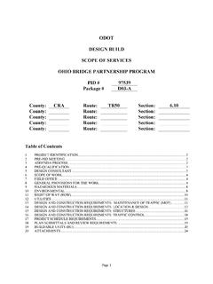
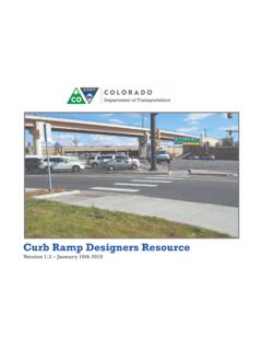
3 BogardD. Fisher6"T6"5"TT4"Slope 12:1 Slope 12:1 TYPE 2 TYPE 2-ATYPE 2-BConcrete PavementWearing CourseCourseConcrete BaseConcrete PavementTYPE 1 NOTESLEGENDTYPE 3 TYPE 3-ATYPE 3-B PavementSurface of PavementSurface of 42 2" of curb " " rad. " " of " " rad. " " rad. " " rad. " " rad." PavementSurface of Wearing CourseConcrete Base Course " " of 2 Sections in PlansAs Shown on TypicalSlope 12:1 TYPE 4 " " of concrete PavementTYPE 4-A " of 3" CourseConcrete Base CourseTYPE 4-B16" " " SealerMaterial, Item Joint PavementSurface of Approach SlabPavement/TYPE 4-C118" " " , Item Joint PavementSurface of Pavement1" " , ItemPreformed JointJoint SealerPavementEarthTYPE 6 TYPE 7 BasePavementSurface of Sections in PlansAs Shown on TypicalConcreteAshphalt PavementSurface of 12"1" " SealerMaterial, Item Joint Pavementor ShoulderAsphalt Pavement111 TYPE 8 Surface MaterialBituminousRigid PavementV1222 TOLERANCES: gutter PLATE THICKNESS: JOINTS: GENERAL: 12"12"Joint Sealer Gutters: 0 to + ".
4 " to + ". 32-1 Curbs: TOLERANCES: Dimensional tolerances are as follows:otherwise shown on the PLATE THICKNESS: Thickness of gutter plate "T" shall be 9" unless Item expansion joint material shall meet the requirements of pavement. and gutter section at expansion joints and to the surface of the above the flow line of the gutter . Dowel bars shall be used in the curb face a sufficient distance to seal the joint to an elevation of a least 2" the joint seal will extend the full width of the gutter and into the curb shall be constructed in the curb and gutter section in such a manner that JOINTS: 1" expansion joints shall extend up to the top of the curb and edge of the curb and gutter to be used, also the thickness of the edge of the pavement or the various types of pavement. The typical section of the project shows the GENERAL: This drawing shows alternate types of curb that may be used on curb -and-gutterCombinedSections in PlansAs Shown on Typical 6"4"6"1"9"6"6"6"5"6"4"4"6"5"4"1"6"6"5"6" 1"6"8"10"1"9"9"1" 'Section in PlansAs Shown on Typical 6"6"Section in PlansAs Shown on Typical Section in PlansAs Shown on Typical TPavementSurface of Sections in PlansAs Shown on TypicalTYPE 93"8"12" 2"1" the curb -and- gutter and rigid pavement is less than 7".
5 Bolts shall be omitted when the vertical overlap ("V" in detail below) concrete , a butt joint shall also be provided. However, tie bars or hook existing rigid base or pavement that is to be surfaced with asphalt If the combined curb -and- gutter adjoins a new rigid base or an intervals of 5'. See SCD for details of tie bars and hook existing rigid pavements, with tie bars or hook bolts provided at Butt joints shall be provided between combined curb -and- gutter and new and concrete are required, as detailed, for the full height of rigid pavement of the curb that is adjacent to a flexible pavement type. Both Expansion joint material and joint sealer are not required for the portion Roadway Cross SlopeCross Slope to MatchTPavementSurface of Sections in PlansAs Shown on Typical3"9" 2"TYPE 101" " " " , Item Joint PavementSurface of PavementTYPE 10-A112"Joint Sealer6"1"6"2" "44 14" " , Item Joint PavementSurface of PavementTYPE 10-B1 Joint Sealer1"6"2"4"2'-6" unless otherwiseshown on plans5"5"2'-6" unless otherwiseshown on plans2'-6" unless otherwise shown on plans5"4"5"4"ENGINEERINGROADWAYOFFICE OF13 NEW curb RAMPS(with Detectable Warnings)STANDARD ROADWAY CONSTRUCTION DRAWINGSCD DATETRANSPORTATION ADMINISTRATORSTATE OF OHIO DEPARTMENT OF1-21-2022 Brenton BogardD.
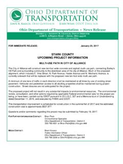
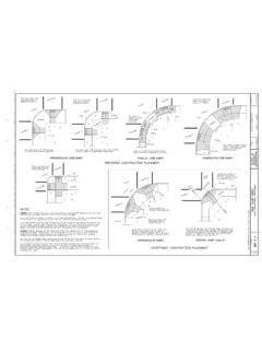
6 Fisherat locations with wide curb ramps with flared sidesradius and where sidewalks are on streets having wide turningis wide enough to accommodate ramp curb ramps with returned curbs where bufferwhere curb radii are less than 20'-0" . Parallel or Combination curb ramp type. Avoid usingD ramp may be constructed as either a Perpendicular,constraints prohibit other designs. The diagonal Type Use this design only for existing walks, and when siteto encroach into adjacent traveled within crosswalk limits so as notturning radius where user is able toAcceptable design on corners with wideNOTESPERPENDICULAR curb RAMPSPREFERRED CONSTRUCTION PLACEMENTPARALLEL curb RAMPSCOMBINATION curb RAMPSACCEPTABLE CONSTRUCTION PLACEMENTDIAGONAL RAMP (Type D)PERPENDICULAR RAMPSPAYMENT:GENERAL:details on Sheet using Type A1 Construct each curbStreetCrosswalkCurbCrosswalkSidewalk 4'-0" on Sheet using Type A1 Construct each curbStreetCrosswalkCrosswalk4'-0" '-0" RampsDouble ParallelTwo sets ofCurbStreetCurb5'-0" '-0" '-0" on Sheet using Type C1 Construct each curbCrosswalkRadialRadialCrosswalkCrossw alkCurbStreet4'-0" '-0" min.
7 (Bypass) When RequiredSidewalk Wideningdetails on Sheet using Type A1 Construct each curb1'-0" preferred prevent usingretrofit only whereAcceptable design for4'-0" Space4'-0" min. CrosswalkwalkCross-4'-0" min. LandingSidewalkCurbdetails on Sheet using Type A2 Construct each curbCrosswalkStreetCrosswalkCurbBufferSi dewalksidewalks , and sufficient streets have wide turning curb ramp placement where a minimum of 4 removal of existing pavement (Item 202) to the nearest joint, or if no joint exists, Item 608 Detectable Warning, Square Foot. The work to cast the tiles in place will also acheive ADA compliance, measure and pay for the strip of detectable warnings as For at-grade crossing locations where only detectable warnings are required in order to of existing curb , walk (or existing curb ramps) are paid under Item beyond the shaded ramp/landing area is paid for as curb (609) and walk (608).
8 Removal forming, and finishing required within the shaded warnings, landing areas and any additional materials, installation, grading, Item 608 curb Ramp, Square Foot. This includes the cost of any curb or curb and gutter , PAYMENT: Measure and pay for the ramp area within the shaded limits of this drawing as ramps if existing field conditions warrant with the approval of the be constructed to ADA standards. The contractor may adjust the placement of curb project plans to assure that the design is appropriate for site constraints and all items curb ramps added to an existing intersection or walk should be individually detailed on the as specified to be constructed in the locations shown on the project plans. curb ramp types are shown on Sheet 2 and include Perpendicular, Parallel, and combined typesconstruction, including the installation of detectable : This drawing shows curb ramp types details and placement examples for curb ramp 13:1 max.
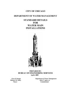
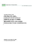
9 THIS DRAWING REPLACES DATED 7-20-2018. ENGINEERINGROADWAYOFFICE OF23 NEW curb RAMPS(with Detectable Warnings)STANDARD ROADWAY CONSTRUCTION DRAWINGSCD DATETRANSPORTATION ADMINISTRATORSTATE OF OHIO DEPARTMENT OF1-21-2022 Brenton BogardD. FisherSee Sheet 3 for :1 :1 :1 :1 :1 :1 :1 :1 :1 :1 :1 GrassGrassGrassSidewalkSidewalkSidewalkS treet Slope :1 :1 :1 :1 :1 :1 combined curb RAMP DETAILSPERPENDICULAR curb RAMP DETAILSPARALLEL curb RAMP DETAILSDCCBBAA64:1 max. 64:1 max. 64:1 max. 64:1 max. 13:1 max. 64:1 max. 13:1 max. 64:1 max. 13:1 max. 64:1 max. 64:1 max. 64:1 max. 13:1 max. 64:1 max. 64:1 max. Type C1 ( combined with flared sides)Type B3 (Single sided Parallel) :113:1 max. :1 SidewalkDof the RampCurb Follows SlopeJOINTS:SURFACE TEXTURE:DRAINAGE:DETECTABLE WARNINGS:Type C2 ( combined with returned curb )Type B2 (Double sided Parallel)Type B1 (Single sided Parallel)Type A1 (Perpendicular with flared sides)Type A2 (Perpendicular with returned curb )NOTES CONTINUEDG rade Break4'-0" '-0" '-0" '-0" '-0" '-0" '-0" '-0" 5'-0" '-0" '-0" '-0" '-0" '-0" '-0" HeightCurb5'-0" '-0" '-0"4'-0" '-0" '-0" Landing5'-0" '-0" " Curb4'-0" " CurbLanding5'-0" '-0" '-0" slope changes, and do not necessarily indicate joint concrete walks.
10 Lines shown on this drawing indicate the ramp edgesa " Item expansion joint filler around the edge of ramps built inand consistent with Item requirements for a new concrete walk. ProvideJOINTS: Provide expansion joints in the curb ramp as extensions of walk jointsto the ramp slopes to be rougher than the adjacent TEXTURE: Texture concrete surfaces by coarse brooming transversegutter, and 2) gutter and ramp, are not allowed. slopes. Vertical change in level exceeding " between the 1) pavement andallows for proper drainage, without exceeding allowable cross slope or rampDRAINAGE: Contractor is to ensure the base of each constructed curb ramp as per manufacturer's written instructions. approved materials, as shown on Sheet 3. Install these proprietary products DETECTABLE WARNINGS: Install Detectable Warnings on each curb ramp with and running landings shall be 4' min.