Transcription of `Ohm’s Law III -- Resistors in Series and Parallel
1 `Ohm s Law III -- Resistors in Series and Parallel by Dr. James E. Parks Department of Physics and Astronomy 401 Nielsen Physics Building The University of Tennessee Knoxville, Tennessee 37996-1200 Copyright August, 2007 by James Edgar Parks* *All rights are reserved. No part of this publication may be reproduced or transmitted in any form or by any means, electronic or mechanical, including photocopy, recording, or any information storage or retrieval system, without permission in writing from the author. Objectives The objectives of this experiment are: (1) to understand and use Ohm s Law, (2) to learn, understand, and use Resistors connected in Series and Parallel , (3) to learn the basic concepts and relationships of current and voltage measurements in DC circuits containing Resistors wired in Series and Parallel , (4) to learn the relationships of the total resistance of Resistors connected in Series and Parallel , and (5) to learn to use ammeters, voltmeters, ohmmeters, and multimeters to properly measure voltages, currents, and resistances.
2 Introduction Most common household electrical circuits are made of many devices connected in Parallel . Each device is hooked to the power source in Parallel with all the other devices, each connected to the same voltage source and availing itself of the same voltage. Each device has its own characteristic resistance, and therefore each draws from the source a different amount of current, depending on its resistive value. While the voltage being accessed is nearly the same for all devices, the amount of current drawn from the source increases as each device draws its respective current based on its resistance. As a result as more and more devices are connected in Parallel , the total amount of current drawn from the source increases. It thus has the effect of causing the resistance to decrease with each additional resistance added. Additional devices added to a circuit , require additional current from the source until something is overloaded.
3 More current is required beyond that which can be supplied by the source or carried by the conductors without burning up. Series circuits are not as common, except for old time Christmas tree lights that are a challenge to fix when one unknown bulb has burned out and all the rest fail to work. Ohm s Law III Resistors in Series and Parallel However, all wires that make connections and the connections themselves qualify as Series resistance. Wires have resistance that depend on wire size, length, and type of material. Wires add Series resistance to circuits, just as good and bad connections add also. In order to fully understand electrical circuits and their behavior, one must first understand Ohm s Law and the principles regarding Resistors in Series and Parallel circuits. Theory Ohm s Law Ohm s Law is the relationship between the current I flowing through a resistance R and the potential drop across it V.
4 The current is directly proportional to the potential difference across the resistance and is inversely proportional to the resistance, VI = R. (1) As an alternative, Ohm s Law may be stated as: The potential difference V across a resistance is directly proportional to the current I flowing through the resistance and the resistance R, or . (2) V = I R Ohm s Law can be rearranged to define the resistance R so that VR = I. (3) If the potential difference across the resistance is measured in volts (V) and the current flowing through the resistance is measured in amperes (A), then the resistance values will be in units of ohms.
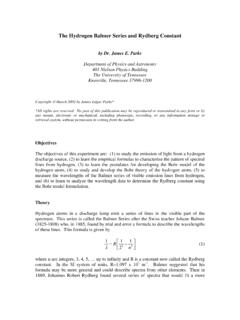
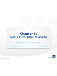
5 Resistors in Series Figure 1 shows 3 Resistors , R1, R2, and R3, connected in Series in a closed circuit powered by a single battery or Emf source. In this circuit the current supplied by the battery flows through each resistor , with the current in each resistor being the same. If the current supplied by the battery is IT, the current in each resistor is I1, I2, and I3, and they are all one and the same, then . (4) T12I = I = I = I3 Ohms Law III Series Parallel 3/3/08/5:33 PM 2 Ohm s Law III Resistors in Series and Parallel VRRR2132EV1V3V1 VTI1 IIT2I3 III Figure 1. Three Resistors R1, R2, and R3 connected in Series . The voltage drop across the battery VT will be the total sum of the individual drops across each of the 3 Resistors , and . (5) T12V = V + V + V3T1233 where V1 is the potential difference across R1, V2 is the potential difference across R2, and V3 is the potential difference across R3.
6 From Equation 2, , (6) TTV = I R , (7) 11V = I R , (8) 22V = I Rand . (9) 33V = I R Substituting these equations into Equation 5 gives (10) TT112233I R = I R + I R + I Rand since IT = I1 = I2 = I3 . (11) T12R = R + R + R Therefore, when Resistors are connected in Series , the total resistance is just the sum of the individual resistances.
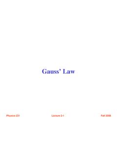
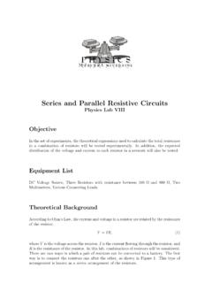
7 While this has been shown for 3 Resistors , the total resistance of any number N (N 2) of Resistors connected in Series , end to end, can be found using the same general procedure. Therefore for Resistors connected in Series Ohms Law III Series Parallel 3/3/08/5:33 PM 3 Ohm s Law III Resistors in Series and Parallel NTi=1R = Ri . (12) Resistors in Parallel Resistors are connected in Parallel when one end of each resistor is connected to a common point and each of their other ends is connected to another common point as shown in Figure 2. The current IT that is supplied by the battery is divided into 3 separate currents, I1, I2, and I3, each flowing through Resistors R1, R2, and R3 respectively. After flowing through the Resistors , the 3 currents rejoin into a common current, IT, or that current flowing back to the battery.
8 The total current flowing in the circuit is the sum of the separate currents flowing through the Resistors , . (13) T12I = I + I + I3 RRRIIII1322T31E Figure 2. Three Resistors R1, R2, and R3 connected in Parallel showing the flow of current. From Equation 1 the total current is related to the total voltage and total resistance by TTTVI = R. (14) and the current, potential difference, and resistance of each separate resistor is given by 111VI = R, (15) Ohms Law III Series Parallel 3/3/08/5:33 PM 4 Ohm s Law III Resistors in Series and Parallel 222VI = R, (16) and 333VI = R.
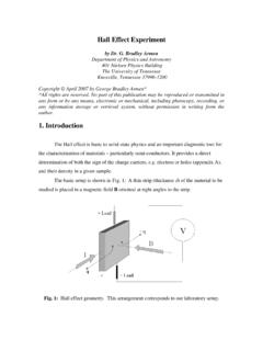
9 (17) Substituting these equations into Equation 13 3T12T12 VVVV= + + RRRR33. (18) The voltage drops across the battery and Resistors are all equal, and as illustrated in Figure 3, . (19) T12V = V = V = V VRRR2132EV1V3V1VT Figure 3. Three Resistors R1, R2, and R3 connected in Parallel showing the potential differences all being equal. Since all the potentials are equal Equation 18 reduces to T121111= + + RRRR3 (20) which is the equation for the total resistance of 3 Resistors connected in Parallel . As was the case for Series Resistors , the total resistance of any number N (N 2) of Resistors Ohms Law III Series Parallel 3/3/08/5:33 PM 5 Ohm s Law III Resistors in Series and Parallel connected in Parallel can be found using the same general procedure and will result in the relationship Ni=1Ti1 = RR1.
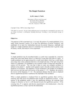
10 (21) In circuits with combinations of Resistors in Series and Parallel , the total resistance can be found by breaking the circuit down into its simplest unit consisting of either resistor in Series or Parallel and then adding its total resistance back into the next simplest unit and finding its total resistance, and so on until the entire circuit has been reconstructed. Apparatus The apparatus is shown in Figure 4 and consists of: (1) 2 Meterman Model 15XP digital multimeters, DMMs, (2) a prototype circuit board with banana jacks for wiring the circuits, (3) a Pasco model PI-9877 power supply, (4) stackable double banana plugs with Resistors or shorting bars (jumper wires) mounted, and (5) assorted leads with banana plugs. These components have been chosen to minimize problems with improper use, while at the same time providing good results for analysis and learning the concepts.