Transcription of Oilfield Servicing Equipment 70 & 80 Series Tubing …
1 Oilfield ServicingEquipment70 & 80 SeriesTubing Blocks Maintenance Requirements Disassembly Instructions Inspection Requirements Maintenance AlertsCrosby Products Distributed by:Table of ContentsGeneral Cautions and Warnings ..1 Operation Information ..4 Preventive Maintenance ..5 McKissick 70 Series Tubing Blocks Disassembly Instructions ..6 - 7 Assembly Instructions ..8 - 9 Inspection Requirements ..10 - 15 Parts List ..16 - 18 McKissick 80 Series Tubing Blocks Disassembly Instructions ..19 Assembly Instructions ..20 - 21 Inspection Requirements ..22 - 27 Parts List ..28 - 30 Maintenance Alerts ..31 - 34 Crosby Testing Information ..35 - 36 Interchangeability Information .. Products are available from leading Sling Fabrication Houses and Industrial Office2801 Dawson Road, Tulsa, OK 74110P: (918) 834-4611 F: (918) 832-0940 email: United States:Plants and FacilitiesCrosby Canada:Crosby Europe:CANADA / Crosby Canada145 Heart , Ontario, Canada L6W 3K3tel.
2 (905) 451-9261 fax (877) / McKissick Products2857 Dawson , OK 74101-5000 TEXAS / Lebus Fisher , TX 75604-4709 ARKANSAS / National Swage W. Main , AR 72076-4213 TEXAS (Dallas)2101 Exchange TX 76011-7823 ILLINOIS (Chicago)16868 S. Lathrop , IL 60426-6031 GEORGIA4723 Fulton Industrial , GA 30336-2433 CALIFORNIA (Los Angeles)5980 Boxford , CA 90040-3006 PENNSYLVANIA1505 S. 19th , PA 17104-2920 WASHINGTON (Seattle)2505 Frank Albert Rd. EastFife, WA 98424-3910 BELGIUMI ndustriepark Zone b N 262220 Heist-op-den-BergP: (+32) (0)15 75 71 25F: (+32) (0)15 75 37 21, rue du Petit AlbiParc d Affaires Silic95800 Cergy - St. ChristopheP: (+33) (0)1 34 201 180F: (+33) (0)1 34 201 NETHERLANDSC elsiusstraat Box 5186710 BM EdeP: (+31) (0)318 690 999F: (+31) (0)318 690 KINGDOM Station StreetCradley HeathWest Midlands B64 6 AJP: (+44) (0)1226 290 516F: (+44) (0)1226 240 this QR code with your smart device to view our corporate 2015 The Crosby Group LLCAll Rights Reservedrev.
3 6 General Cautions and WarningsAll products manufactured by The Crosby Group LLC are sold with the express understanding that the purchaser is thoroughly familiar with the safe and proper use and application of the for the use and application of the products rests with the of the product can occur due to misapplication, abuse, or improper maintenance. Product failure could allow property damage, personal injury, or are numerous government and industry standards that cover products made by Crosby. This catalog makes no attempt to reference all of them. We do reference the standards that are most frequently asked shown in Crosby Group literature are applicable only to new or in as new condition limit ratings indicate the greatest force or load a product can carry under usual environmental loading and extraordinary conditions must be taken into account when selecting products for use in a general instructions deal with the normal installation, operation, inspection, and maintenance situations encountered with the Equipment described herein.
4 The instructions should not be interpreted to anticipate every possible contingency or to anticipate the final system, crane or configuration that uses this LOAD The load resulting from a constantly applied force or LOAD LIMIT The maximum mass or force which the product is authorized to support in general service when the pull is applied in-line, unless noted otherwise, with respect to the center line of the term is used interchangeably with the following terms:1. WLL2. Rated Load Value3. SWL4. Safe Working Load5. Resultant Safe Working LoadWORKING LOAD The maximum mass or force which the product is authorized to support in a particular LOAD The average force applied in the performance of a proof test; the average force to which a product may be subjected before deformation LOAD The average load or force at which the product fails, or no longer supports the LOAD A force that results from the rapid application of a force (such as impacting and/or jerking) or rapid movement of a static load.
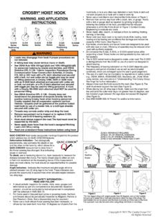
5 A shock load significantly adds to the static (SAFETY) FACTOR An industry term denoting a product s theoretical reserve capability; usually computed by dividing the catalog Ultimate Load by the Working Load Limit. Generally expressed for blocks as a ratio of 4 to block An assembly consisting of a sheave(s), side plates, and generally an end fitting (hook, shackle, etc.) that is used for lifting, lowering, or applying Failure to read, understand and follow these instructions may cause death or serious injury. This Equipment is not designed for and should not be used for lifting, supporting or transporting humans. Only trained and competent personnel should install, operate, inspect and repair this Equipment .
6 Modification to upgrade, repair or otherwise alter this Equipment shall be authorized only by the original Equipment manufacturer or qualified professional engineer. If this block is a component in a system, the system designer will be responsible for passing on to the end user the information contained in this !For maximum safety and efficiency, tackle block systems must be properly designed, used, and maintained. You must understand the use of tackle block components in the system. These instructions provide this knowledge. Read them carefully and parts of these instructions must use technical words and detailed explanations. NOTE: If you do not understand all words, diagrams, and definitions DO NOT TRY TO USE A TACKLE block SYSTEM!
7 For further assistance, call:In Crosby Engineered Products Group at CANADA Crosby Canada (905) EUROPE Crosby Europe you read instructions, pay particular attention to safety information in bold INSTRUCTIONS FOR FUTURE USE DO NOT THROW AWAY!2 Copyright 2015 The Crosby Group LLCAll Rights Reservedrev. 6 Oilfield Servicing EquipmentMcKissick Oilfield Servicing Equipment Series 70 Streamlux Tubing Blocks with Spring Loaded Duplex Hook Spring loaded duplex hook assuring ample travel for efficient Tubing operations. No load carrying threads. Exclusive E-Z* opening guards, no bolts to pull out and lose. Feature gives fastest possible exposure of sheave cluster for quick reeving. Extremely short overall length, extra weight, and excellent balance for fast non-wobbling falls.
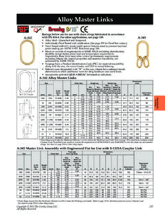
8 Extra large sealed sheave bearing diameters for fully rated capacities. Tapered roller thrust bearing in hook. Duplex hook for easy elevator operation, locks in six or eight positions. Convenient rod hook clevis available as shown on Figure 73A. Completely streamlined, no projections. Flame hardened steel sheaves grooved for proper wire line size. Threaded hook parts precision machined and individually fitted for maximum safety. Hook and case assembly interchangeable with the Series 80 Streamlux Tubing Blocks. All blocks available with additional cheek 73 Awith Rod Hook ClevisFig. 73* (in.) RopeSize(in.)APIW orkingLoad(Tons)Rod HookClevisWorkingLoad Limit(lbs.)Weight(lbs.)CenterPinDiameter (in.)Dimensions(in.)
9 - 3/4257,00054074 02-3/446-1/243168-1/412-1/4731435/8 - 3/4357,0007209202-3/450-1/446-3/81611-1/ 815-1/8721723/4 - 7/8407,000112 014402-3/457-7/8541910-7/1614-7/16731733 /4 - 7/85015,000140017202-3/460-5/856-1/81914 18722027/8 - 15015,000146019353-15/1664-3/859-3/82311 -7/815-7/8732037/8 - 17525,000195024253-15/1666-5/861-5/82316 -1/820-1/8722421 1-1/87525,000216028204-1/471-1/466-1/427 11-1/415-1/4732431 - 1 1/810070,000268732744 1/475 1/269 1/427 15 1/419 1/4732431 - 1 1/812570,000268732744 1/475 1/269 1/427 15 1/419 1/4733031 - 1 1/415070,000425051225 5/886 7/878 3/832 1/416 3/820 3/8743041 - 1 1/415070,000484757035 5/886 3/478 1/432 3/820 1/224 1/2733031 - 1 1/417570,000425051225 5/886 7/878 3/832 1/416 3/820 3/8743041 - 1 1/817570,000484757035 5/886 3/478 1/432 3/820 1/224 1/23 Copyright 2015 The Crosby Group LLCAll Rights Reservedrev.
10 6 Oilfield Servicing EquipmentMcKissick Oilfield Servicing Equipment Series 80 Streamlux Tubing Blocks with Locking Duplex Swivel Hook Exclusive E-Z* opening guards, no bolts to pull out and lose. Feature gives fastest possible exposure of sheave cluster for quick reeving. Extremely short overall length, extra weight, and excellent balance for fast non-wobbling falls. Extra large sealed sheave bearing diameters for fully rated capacities. Tapered roller thrust bearing in hook. Duplex hook for easy elevator operation, locks in six or eight positions. Convenient rod hook clevis available as shown on Figure 83A. Completely streamlined, no projections. Flame hardened steel sheaves grooved for proper wire line size.