Transcription of OM Isolation Module Tester - Western Plows
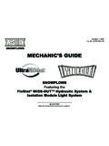
1 Western PRODUCTS, BOX 245038, MILWAUKEE, WI 53224-9538 A DIVISION OF DOUGLAS DYNAMICS, 's Manualfor Isolation Module Tester CAUTIONRead this document before testing anyWESTERN snowplows. CAUTIONSee your Western outlet for applicationrecommendations. The Selection List hasspecific vehicle and snowplow MODULETESTER11224433 TURN SIGNALLOW BEAMHIGH BEAMDOUGLAS DYNAMICS, L. L. LIGHTSTURN SIGNALLOW BEAMHIGH BEAMLOW BEAMHIGH BEAMHIGH BEAM #2 LOW BEAMHIGH BEAMHIGH BEAM #2 plow ATTACHEDPLOWONOFFHEAD LAMPNEG (-)POS (+)COMMONATTACHEDDEDICATED DRLBULB SYSTEMOFFONONOFFHIGHBEAM #2 PART NUMBER 26471 CONTROL POWERIGNITION SWITCHHEAD LAMPLOWHIGHPARK LAMPOFFIGNITIONOFFONSWITCHTURN SIGNALRIGHTLEFTONLit. No. 64432 April 28, 2003 TABLE OF CONTENTSS afety 1 Test Preparation .. 5 Isolation Module On-Vehicle Test .. 5 Isolation Module 26400 (White Label) Off-Vehicle Test .. 7 Isolation Module 27781 (Light Green Label) Off-Vehicle Test .. 8 Lit. No.
2 64432 April 28, 2003 Lit. No. 644321 April 28, 2003 SAFETY DEFINITIONSNOTE: Identifies tips, helpful hints, andmaintenance information the owner/operatorshould YOU BEGIN Park the vehicle on a level surface, place shiftlever in PARK or NEUTRAL and set parking brake. WARNINGI ndicates a potentially hazardous situation,that if not avoided, could result in death orserious personal injury. CAUTIONI ndicates a situation that, if not avoided, couldresult in damage to product or SAFETY Wear only snug-fitting clothing while working onyour vehicle or snowplow . Do not wear jewelry or a necktie, and secure long hair. Wear safety goggles to protect your eyes frombattery acid, gasoline, dirt and dust. Avoid touching hot surfaces such as the engine,radiator, hoses and exhaust pipes. Always have a fire extinguisher rated BC handy,for flammable liquids and electrical AND EXPLOSIONBe careful when using gasoline. Do not use gasolineto clean parts.
3 Store only in approved containers awayfrom sources of heat or SAFETYFUSESThe vehicle control harness contains two automotive-style fuses. One fuse is for the snowplow park/turnlamp power and the other is for the snowplow controlpower. If a problem should occur and fusereplacement is necessary, the replacement fuseshould be of the same value as the original. Installinga fuse of a larger value could damage the system. WARNINGG asoline is highly flammable and gasolinevapor is explosive. Never smoke while workingon vehicle. Keep all open flames away fromgasoline tank and lines. Wipe up any spilledgasoline immediately. CAUTIONB atteries normally produce explosive gaseswhich can cause personal injury. Therefore, donot allow flames, sparks or lit tobacco to comenear the battery. When charging or workingnear a battery, always cover your face andprotect your eyes, and also provide contain sulfuric acid which burnsskin, eyes and the battery before removing orreplacing any electrical WARNINGL ower blade when vehicle is changes could change hydraulicpressure, causing the blade to dropunexpectedly or damaging hydrauliccomponents.
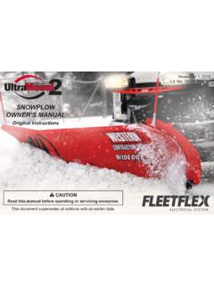
4 Failure to do this can result inserious personal injury. WARNINGThe Tester shall keep bystanders clear of theblade during this test. Do not stand between thevehicle and the blade. A moving or falling bladecould cause personal injury. CAUTIONB efore starting any test, the snowplow must beproperly attached to the No. 644322 April 28, 2003 WARNING/CAUTION & INSTRUCTIONLABELSB ecome familiar with and inform users about thewarning and instruction labels on the back of System with Straight BladesWarning/Caution LabelUniMount System withStraight BladesSAFETYINSTRUCTIONSPull and hold Lock Pin out; then rotate Handle DOWN and release Lock Pin. It must lock into LOWER hole. Push down top of Shoe; Shoe will be on the ground. Repeat steps 2 and 3 on other side of plow . Back vehicle away. After lowering blade and turning control off, disconnect electrical 3 STEP 2 STEP 1 After seating plow horns in receiver brackets, pull Handle up; Shoe will lift off the and hold Lock Pin out; then rotate Handle UP and release Lock Pin.
5 It must lock into UPPER hole. Stand Hook must grip Receiver in electrical connections. Repeat steps 1 and 2 on other side of 1 STEP 2 STEP 3 ONOFFOFFONR eceiver PinStand HookHandle(Pull)Lock PinShoeHandleMOUNTING plow (ON) Read Owner's Manual for complete plow (OFF) Read Owner's Manual for complete : US 4,999,935; 5,420,480; RE 35,700; 6,145,222; 6,209,231; 6,253,470; 6,526,677; CAN 2,060,425; patents Instruction LabelInstruction LabelLit. No. 644323 April 28, 2003 UltraMount Systemwith MVP SnowplowWarning/Caution LabelUniMount Systemwith MVP SnowplowSAFETYI nstruction LabelINSTRUCTIONSPull and hold Lock Pin out; then rotate Handle DOWN and release Lock Pin. It must lock into LOWER hole. Push down top of Shoe; Shoe will be on the ground. Repeat steps 2 and 3 on other side of plow . Back vehicle away. After lowering blade and turning control off, disconnect electrical 3 STEP 2 STEP 1 After seating plow horns in receiver brackets, pull Handle up; Shoe will lift off the and hold Lock Pin out; then rotate Handle UP and release Lock Pin.
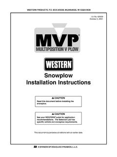
6 It must lock into UPPER hole. Stand Hook must grip Receiver in electrical connections. Repeat steps 1 and 2 on other side of 1 STEP 2 STEP 3 ONOFFOFFONR eceiver PinStand HookHandle(Pull)Lock PinShoeHandleMOUNTING plow (ON) Read Owner's Manual for complete plow (OFF) Read Owner's Manual for complete : US 4,999,935; 5,420,480; RE 35,700; 6,145,222; 6,209,231; 6,253,470; 6,526,677; CAN 2,060,425; patents Instruction LabelLit. No. 644324 April 28, 200327155 ONOFFC onnectingPinJackRetainerJack SleeveJackJack HandlePlow GearReceiver Patents 4,999,935; 5,420,480; 6,253,470; RE35,700; CAN Patent 2,060,425; and other patents Owner's Manual for Complete Instructions4. Loosen one jack handle and slide jack sleeve down below jack retainer. Remove jack and retighten jack handle. Repeat for other jack and store Connect all electrical cables from vehicle to Make certain both connecting pins are fully Drive vehicle slowly to completely insert attachment arms into receiver assembly Twist both connecting pins to release spring tension, then push plow gear toward vehicle so connecting pins fully engage holes in attachment While pushing plow gear toward vehicle to release connecting pin tension, pull connecting pin out on one side and twist pin handle to keep pin retracted.
7 Repeat procedure for other connecting Disconnect all electrical Put blade on ground using LOWER/ FLOAT on snowplow control. Leave control ON and in Attach jacks. Loosen jack handle, put jack on ground, and raise jack sleeve until fully engaging jack retainer. Tighten jack handle. Repeat for other Back vehicle away from See Owner's Manual for proper snowplow snowplow is for personal/homeowner use snowplow is for personal/homeowner use snowplow is for personal/homeowner use Personal PlowWarning/Caution LabelInstruction LabelSAFETYLit. No. 644325 April 28, 2003 TEST PREPARATION When connecting the Isolation Module Tester tothe battery, connect the red clip to the positiveterminal and the black clip to the negativeterminal. Connect the black clip last. Whendisconnecting, disconnect it first. If an Isolation Module Tester lamp ( Tester lampsare white, Tester LED's are green and slightlysmaller) does not come on, the fault could be anopen lamp element, an open circuit, or both.
8 All vehicle lamps must be operational. An openlamp may cause false test results. The Isolation Module Tester is protected by a fuseinside the Tester that automatically resets itself. Ifthe fuse activates, disconnect power from theIsolation Module Tester and wait several resume the test. The table below lists the user-serviceable partsinside the Isolation Module Module TEST PROCEDURE CAUTIONRead this document before testing anyWESTERN Module ON-VEHICLE TESTSet-UpBefore connecting the Isolation Module Tester to theIsolation Module , ensure the Isolation Module Testerswitches are in the following the Isolation Module Tester to the IsolationModule as follows:1. Connect the Isolation Module Tester power cableto a 12-volt power source by attaching the redalligator clip to positive and the black alligator clipto Connect the Adapter Cable (part number 26472)to the Isolation Module Tester harness Connect the molded connector of the AdapterCable to the vehicle lighting harness connectorlocated at the grille of the vehicle.
9 Isolation ModuleTester harnesses 1, 3, and 4 are not used for Procedure1. Turn the vehicle s ignition on, but do not startengine. Verify the vehicle s lights function properlyby cycling the vehicle s park, turn, hazard, highbeams, low beams, and DRL lamps. Then placethe vehicle s headlamp switch in the low beamposition. Turn off all vehicle lighting. Repair orreplace any defective vehicle lamps Turn the Isolation Module Tester power switchto the ON position. Only the power indicatorshould Module Tester Switch Position power OFF PARK LAMPS OFF HEADLAMPS LOW plow ATTACHED NO IGNITION SWITCH OFF HEADLAMP COMMON NEG (-) HIGH BEAM #2 OFF DEDICATED DRL BULB SYSTEM OFF REPLACEMENT PARTS PART QTY DESCRIPTION 26475 5 REPLACEMENT LAMPS 26476 1 REPLACEMENT HARNESS KIT 26517 1 REPLACEMENT CASE W/LABEL Lit.
10 No. 644326 April 28, 2003 Isolation Module TEST PROCEDURE3. Turn on the vehicle s parking lamps. Verify thevehicle s parking lamps are Turn on the vehicle s headlamps. Verify thevehicle s low beams are Place the Isolation Module Tester PLOWATTACHED switch in the YES position. Verify thevehicle s low beams go off and the followingIsolation Module Tester indicators are lit: PLOWATTACHED, plow PARK LIGHTS, and both plowLOW Place the vehicle s headlamps in the high beamposition. The Isolation Module Tester plow HIGHBEAM indicators should Turn on the vehicle s left turn signal. Verify thevehicle s left turn signal is functioning properly andthe Isolation Module Tester left TURN SIGNAL indicator is lit. Turn off vehicle s left turn Turn on the vehicle s right turn signal. Verify thevehicle s right turn signal is functioning properlyand the Isolation Module Tester right TURNSIGNAL indicator is lit. Turn off vehicle s right Activate the vehicle s four-way flashers.