Transcription of ONAN RV GENERATOR QUICK …
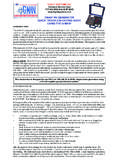
1 ONAN RV GENERATOR QUICK troubleshooting GUIDEUSING THE G-MAN INTRODUCTIONThe G-MAN is designed with the RV GENERATOR service technician in mind. Diagnosis can account for up to 80% of ser-vice labor cost. This versatile service tool speeds the troubleshooting process by eliminating guesswork and pinpointing problems. troubleshooting is broken down into the four specific areas of the ENGINE, ENGINE CONTROL, GENER-ATOR and REGULATOR. GENERATOR control troubleshooting can be complicated by the normal action of the control to prevent starting or cause a shutdown in the event of a problem. This can be a dead end that prevents the troubleshoot-ing process from moving forward without guesswork, jumper wires and/or parts substitution. This approach can be both time-consuming and expensive. What makes the G-MAN unique is its ability to plug in to the GENERATOR s control system and become a part of it, instead of being a circuit board or component tester.
2 You can run the engine without the control board because the G-MAN takes over most of its functions. If any of the signals to the control board are missing, the G-MAN will tell you. If op-eration is normal with the G-MAN but not with the control board plugged in, then you know right away that you have a bad control board. This is known as testing by exception. DISCLAIMER: The G-MAN service tool is designed for use by GENERATOR service professionals and others who are familiar with engine- GENERATOR sets and their controls. Working on engines, generators and their controls presents certain hazards to equipment and personnel. It is assumed that the G-MAN user is adequately trained in the proper use of test equipment and the management of risks inherent in GENERATOR servicing. The G-MAN is not intended for use by the gen-eral public. Flight Systems is not responsible for damage to equipment or injury to personnel, direct or consequential, arising from the use of the G-MAN service tool.
3 Liability is limited to repair or replacement of defective product under the terms of the standard service tool is designed for use ONLY on 120 volt, 50 or 60 Hz, single-phase generators using a 12-volt negative ground electrical STARTEDD etermine the control board part number directly from the board or from the Application Chart. Refer to the Trouble-shooting Chart for test information specific to that board. G-MAN responses are different for different control boards. Connect the appropriate adapter to the G-MAN control harness. CAUTION: Some adapters look similar and have iden-tical connectors, but a different pin assignment. Improper connections can cause damage to the GENERATOR controls and/or to the G-MAN. Such damage is not covered by the proceeding with evaluation of the controls, regulator or GENERATOR , the Onan engine must have oil and fuel, be in running condition and the 12-volt battery charged.
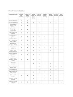
4 The electronic governor, 151-0752, on Models BGM and NHM, Spec B and later, must be functioning properly. This guide does not cover engine maintenance and repair procedures (please refer to the applicable Onan Service Manual for this information). The most common genset problems are caused mainly by lack of use and/or lack of regular monthly exercise and include the following: Low battery voltage because of insufficient charge, worn out battery, faulty cables (partly broken or corroded) or poor connections, resulting in slow cranking and hard starting. Old or contaminated fuel that has gummed up the lines, fuel filter and carburetor. This can cause clogged jets (mixture too lean) and/or a stuck carburetor float resulting in an improper mixture (too rich or too lean) or flooding. Weak spark and/or fouled spark plug(s) causing hard starting and rough running. Stuck automatic choke causing an excessively rich mixture and smoking.
5 Stuck oil pressure switch causing shutdown as soon as the start button is released. Dirty air filter, causing an excessively rich mixture and smoking. Low oil level preventing starting on models equipped with low oil level switch. Wiring harness damage from rodents chewing on the wires. Corrosion of control board or connections from salty air or road chemicals. Dirty and/or oxidized slip rings causing high field circuit the engine has been running for a few minutes, the electric choke heater should begin to open the choke. The choke will take longer to open fully in cold weather. If the choke does not open, it is either stuck or the choke heater is not working. The choke mechanism can be freed up and maintained with Mouse Milk , a high temperature penetrating lubricant. (Available from Flight Systems) If the engine surges or hunts (does not stay at a constant RPM), the cause is likely a gummed-up carburetor or an improperly adjusted governor.
6 These conditions must be SYSTEMS Service 932 9900 (8-4:30 ET M-F) TESTS1. CHECK OIL. Check engine oil level before starting. 2. GAIN ACCESS. Remove panel or cover to gain access to the control board. Some disassembly may be required. The exact procedure depends on the model. Detailed procedures are given in the G-MAN CONNECT G-MAN CONTROL HARNESS. Unplug the control board and connect the G-MAN adapter in its place (the G-MAN does not connect to the remote harness). As soon as the G-MAN has 12-volt power, the 12 VDC POWER indicator will come on. The LOL/LOP SWITCH indicator may also come on, depending on the model. See CONNECT G-MAN REGULATOR & GENERATOR HARNESS. Disconnect the regulator and plug the G-MAN s GENERATOR harness into the plug just removed from the regulator. Plug the G-MAN s REGULATOR harness into the regulator (or a known good regulator).5. CHECK BATTERY VOLTAGE. Connect the negative voltmeter lead to the GROUND jack and the positive lead to the 12 VDC POWER jack on the G-MAN and read the battery voltage.
7 A fully charged battery in good condition should read to VDC. Charge the battery if necessary. IMPORTANT: Disconnect battery charger before proceeding with CHECK CRANKING/ENGINE START. Turn on the IGNITION/FUEL switch. The fuel pump should be heard working. Apply 12 volts directly to the pump if necessary. Press the START button and the engine cranks. If not, check the wiring to the start solenoid. The battery voltage should not fall below VDC during cranking. If so, check the battery condition and cables. The IGNITION/FUEL switch on the G-MAN is used to stop the engine. If the engine starts and runs OK, proceed to step CHECK SPARK. If the engine cranks but does not start, remove a spark plug and check for spark during cranking. Problems such as dirty /worn points or a defective coil can cause loss of spark. On models where the oil level switch is hard-wired to the magneto (KV Spec. C-F, KVC and KVD), low oil level or a stuck switch will inhibit the spark and prevent starting.
8 To check the level switch, unplug the control board and verify that the MAGNETO KILL circuit on the control harness is not grounded. Refer to the troubleshooting CHECK FUEL SYSTEM. If the engine cranks and has spark but does not start, the problem is likely fuel related. This can be confirmed by injecting a small amount of starting fluid into the air intake. If the engine fires and tries to run, it is starving for fuel. Listen for the fuel pump running during cranking. The pressure and flow of the fuel pump (and fuel filter) can be checked by temporarily disconnecting the fuel line to the carburetor. Take adequate precautions when handling fuel. If pressure and flow are normal, reconnect fuel line. Note: If the GENERATOR has not been run for several months, the carburetor float may be stuck closed and /or the jets and needle valves may be gummed up by old fuel that has turned to varnish. These conditions interfere with normal fuel delivery.
9 The automatic choke may be stuck closed or binding so that it does not open as the choke heater warms up (causes smoking). On Models BGM and NHM spec. B and later, make sure that the electronic governor goes to full throttle one second after cranking begins. Any of these conditions will prevent the engine from starting or running smoothly and must be corrected before CHECK FIELD FLASH. Field flash is energized automatically during cranking and until GENERATOR voltage builds. During cranking, the FIELD FLASH indicator should be on, showing that the field flash voltage is actually reaching pin 7 of the regulator. The field flash can also be tested manually at any time by pressing the FIELD FLASH button. Mea-sure the field flash voltage at the FIELD FLASH test jack. It should be 10-11 VDC. If not, check the wiring between the control board field flash output pin on the harness and regulator plug pin CHECK RUN RELAY.
10 After the engine starts, the FIELD FLASH indicator goes off and the RUN RLY indicator comes on. This indicates that the signal required to pull in the run relay in the G-MAN is present (see chart) and that the starter is locked out. If the RUN RELAY indicator does not come on, there may be a problem with the GENERATOR , regu-lator, electronic governor or oil pressure switch, depending on the model. In this case, proceed to the GENERATOR and/or Regulator section (except 300-2784/2943). Also, if the RUN RLY indicator is not on, then the starter is not locked out and damage could result if the starter button on the G-MAN is pressed while the engine is CHECK LOL/LOP SWITCH. As soon as oil pressure builds, the LOL/LOP SWITCH indicator will come on (or go off, depending on model) indicating that the oil pressure switch has been actuated (see chart). Some models use a low oil level switch instead (see step 7 above).