Transcription of OneTechnologyWay P.O.Box9106 Norwood,MA …
1 AN-1319 APPLICATION NOTE One Technology Way P. O . Box 9106 Norwood, MA 02062-9106, Tel: Fax: Compensator Design for a Battery Charge/Discharge Unit Using the AD8450 or the AD8451 by Sandro Herrera and Christopher Lang INTRODUCTION In response to the growing popularity of portable systems, the demand for rechargeable batteries has increased exponentially. The formation and testing of a rechargeable battery requires multiple charge and discharge cycles, during which the current and voltage of the battery must be precisely controlled. Accurately controlling the charge and discharge process extends the life of the battery and maximizes its capacity. Therefore, battery formation and test systems require high precision analog front ends and controllers to monitor and regulate the battery current and terminal voltage. Rechargeable batteries frequently require a constant current -constant voltage (CC-CV) algorithm to charge or discharge them.
2 This algorithm forces a constant current into or out of the battery until its voltage reaches a preset final value. At this point, the system switches to constant voltage mode and provides the necessary current to hold the battery voltage at this final battery formation and test systems implement the CC-CV algorithm using high accuracy feedback loops that control the battery current and voltage. To ensure high battery quality, the feedback loops need to be stable and robust. This application note describes how to design and implement the compensation network for both the constant current and the constant voltage feedback loops in a battery test or formation system using the AD8450 or the AD8451 analog front end and controller. Rev. 0 | Page 1 of 20 AN-1319 Application Note TABLE OF CONTENTS Introduction .. 1 Revision History .. 2 System Overview .. 3 AD8450 and AD8451 Overview .. 3 Power Converter Overview .. 4 Modeling .. 5 Battery.
3 5 Linear Regulators .. 5 Switching Power Converters .. 5 CC and CV Feedback Loops .. 6 Compensator Design .. 8 Uncompensated System .. 8 Compensator Design Steps for the Synchronous Buck/Boost Converter .. 8 AD8450 and AD8451 Bandwidth Considerations .. 14 Design Examples .. 15 Constant current Feedback Loop with a Type II Compensator .. 15 Constant current Feedback Loop with a Type III Compensator .. 16 Special Cases .. 18 Crossover Frequency Before fPP2 .. 18 Linear Regulators .. 18 Steps for Compensating Linear Regulators .. 18 20 REVISION HISTORY 12/14 Revision 0: Initial Version Rev. 0 | Page 2 of 20 Application Note AN-1319 Rev. 0 | Page 3 of 20 SYSTEM OVERVIEW In a battery formation and test system, each charge/discharge unit is comprised of three major components an analog front end, a controller, and a power converter. These components form the CC and CV feedback loops that control the battery voltage and current during the charge/discharge process.
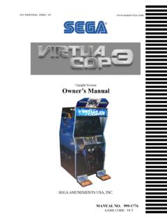
4 The analog front end measures the battery voltage and current and forms the feedback path of the CC and CV control loops (see the Modeling section). The controller compares the measured battery voltage and current to the target values and generates the control signal for the power converter using the CC-CV algorithm. The power converter generates the battery current based on the applied control signal. Figure 1 shows a simplified charge/discharge unit in a battery formation and test system using an AD8450 or an AD8451 analog front end and controller. In this configuration, the power converter extracts power from a common dc voltage bus, which can be shared by multiple charge/discharge units. The shunt resistor (RS) converts the battery current (IBAT) into a voltage across it (VRS) that is read by the AD8450 or the AD8451. Note that the battery current IBAT is the output current of the power converter. The battery voltage is read directly from the battery terminals.
5 In both measurements, Kelvin connections to the shunt resistor and the battery terminals reduce errors due to voltage drops in the wires. Voltage sources ISET and VSET set the target current and voltage for the CC and CV feedback loops, while the external compensation networks set the frequency response of the controller. AD8450 AND AD8451 OVERVIEW The AD8450 and the AD8451 are precision analog front ends and controllers for battery formation and test systems. The analog front end of these devices includes a precision current sense programmable gain instrumentation amplifier (PGIA) to measure the battery current by means of an external shunt resistor (RS in Figure 1) and a precision voltage sense programmable gain difference amplifier (PGDA) to measure the battery voltage. The controllers of the AD8450 and the AD8451 include two feedback control loops a constant current loop (CC) and a constant voltage loop (CV) which transition automatically from CC to CV after the battery reaches the user defined target voltage.
6 The feedback loops are implemented by means of two precision error amplifiers (A1 and A2 in Figure 1). These serve as error amplifiers and external feedback networks that set the frequency response of the CC and CV feedback loops. External voltage references set the battery target current and target voltage for the CC and CV feedback loops. A minimum output selector circuit combines the outputs of the precision amplifiers and implements the CC-CV algorithm of the controller. The controllers of the AD8450 and the AD8451 can be operated in either charge or discharge mode. These modes are selected by switching the state of the MODE pin. Charge and discharge modes use independent compensation networks for the CC and CV loops, and the frequency response of these loops is set independently in each mode. Figure 1. Simplified Charge/Discharge Unit in a Battery Formation and Test System 12685-001 ISETANALOG NOR VSETVCTRLVBATSHUNTRESISTOR +RSIBATPOWERCONVERTERVOUTVCTRLMINIMUMOUT PUTSELECTORCOMPENSATIONNETWORKCOMPENSATI ONNETWORKAD8450/AD8451 PGIAPGDACONSTANT VOLTAGE LOOPCONSTANT current LOOPMODEVRS +VINISVPISVNBVPxBVNxDC BUSVINTVINTISETVSETBVMEAISMEAVVEIVE1A1A2 GDAGIAAN-1319 Application Note POWER CONVERTER OVERVIEW Two types of power converters are commonly used to charge and discharge batteries linear regulators and switching power converters.
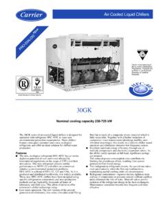
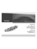
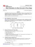
7 Linear regulators are implemented as voltage controlled voltage sources or voltage controlled current sources using a pass transistor. The output current /voltage of these regulators is proportional to their control voltage. While simple to compensate and use, the efficiency of linear regulators tends to be low if the battery voltage and the voltage of the dc bus differ greatly. Figure 2 shows a simple implementation of a charge linear regulator using a voltage controlled current source. In contrast to linear regulators, switching power converters achieve higher levels of efficiency under most conditions but are more complex and more difficult to stabilize. However, due to their increased efficiency, switching power converters are gaining popularity, especially in high power battery formation and test systems. Figure 3 shows a simplified nonisolated synchronous buck/boost switching converter. The control signal (VCTRL), which is generated by the controller (AD8450 or AD8451), sets the duty cycle of the MOSFET switches and the average value of the voltage at Node VM, by means of the pulse width modulator (PWM) of the converter (ADP1972).
8 The inductor (LO) and capacitor (CO) form an LC low-pass filter that averages the voltage at Node VM to generate a low ripple output voltage (VOUT) and output current (IBAT). The nonisolated buck/boost converter is a bidirectional power converter that enables energy recycling in the system. During charge mode, the converter runs in buck mode, such that it pulls current from the dc bus to charge the battery. In discharge mode, the converter runs in boost mode, such that it pulls current from the battery and feeds it to the dc bus. Therefore, in boost mode, the energy stored in the battery is recaptured. Figure 2. Charge Linear Regulator Figure 3. Nonisolated Synchronous Buck/Boost Converter Schematic System Modeling VCTRLVINTO PGIATO PGDABATVOUTM1R2R1Q1RS12685-002 IOUT = IBAT12685-003 VINTO PGIATO PGDABATVOUTVMLOVCTRLM1M2 IOUT = IBATRSCOHVMOSFETDRIVERDC POWER BUSORRECYCLING BUSADP1972 DHPLRev. 0 | Page 4 of 20 Application Note AN-1319 Rev.
9 0 | Page 5 of 20 MODELING designing the compensator for the constant current and constant voltage feedback loops requires linearized models for each of the components in the loops. This section presents these models. BATTERY The small signal model for a battery is simply its internal resistance, RB. While the battery can be modeled as the series connection of the internal resistance and the storage capacitance, at any frequency of interest, the impedance of this connection is approximately RB. Therefore, for simplicity, the storage capacitance is treated as a small signal short. LINEAR REGULATORS The small signal model for a linear voltage controlled current source is a transconductor with transconductance, GM (see Figure 4). The transfer function for this block is GPC(s) = CTRLOUTVI = 1 sGM where: is the time constant of the block and models its finite bandwidth. IOUT is the output current . VCTRL is the input control voltage. Figure 4.
10 Linear Voltage Controlled current Source, Small Signal Model SWITCHING POWER CONVERTERS Figure 5 shows the averaged linearized circuit of the nonisolated synchronous buck/boost converter. In this model circuit, the dc voltage bus, the PWM, and the switches are modeled as a linear amplifier with a voltage gain of AV. In buck (charge) mode, the gain of the amplifier is VIN/VRAMP, where VIN is the voltage of the dc bus and VRAMP is the peak-to-peak voltage of the PWM ramp (4 V p-p in the ADP1972). In boost (discharge) mode, the gain of the amplifier is VIN/VRAMP. The linearized circuit in Figure 5 includes the parasitic resistance of the output inductor, RL, and the output capacitor, RC, of the power converter because they affect the transfer function of the converter. Figure 5. Averaged Linearized Circuit for the Nonisolated Synchronous Buck/Boost Converter In buck (charge) mode, the buck/boost converter has the averaged transfer function shown in Equation 1.